
Product specifications

Installing the VoIP Paging Amplifier
Paging Amplifier Setup
VoIP Paging Amplifier Operations Guide 930185B CyberData Corporation
15
2.2.6 Confirm the IP Address, Test the Audio, and Check the Volume
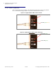
When the Paging Amplifier is operational and linked to the network, use the Reset Test Function
Management (RTFM) switch (
Figure 2-9) on the Paging Amplifier face to announce and confirm the
Paging Amplifier’s IP Address, test that the audio is working, and check the volume.
Figure 2-9. RTFM Switch
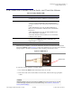
To announce a Paging Amplifier’s current IP address:
1. Press and hold the RTFM switch until it beeps (after one second).
2. Release the switch to hear the IP address announcement, and check the Paging Amplifier
volume.
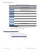
Table 2-6. Paging Amplifier LEDs
LED Color Function
Power Blue/Green The power LED is illuminated a steady blue when the power is
on and blue/green when the amplifier is in the high power mode.
Status Green After supplying power to the Paging Amplifier:
1. The green Status LED illuminates after approximately five
seconds to indicate the start of the firmware verification and load
process.
2. After approximately 15 seconds, the Status LED begins to
blink at one second intervals to indicate the start of the firmware
boot process.
3. After approximately 35 seconds, the Paging Amplifier beeps
once to indicate that it is operational.
4. The Status LED will continue to blink at one second intervals
to indicate normal operation.
Link Green/Yellow The Link LED is illuminated green for a 10Mb link or
yellow/green for a 100Mb link when the network link to the
Paging Amplifier is established.
Activity Green The Activity LED blinks to indicate network traffic.
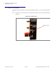
Caution
Equipment Caution: Pressing and holding the RTFM switch for longer than 20 seconds will
restore the Paging Amplifier to the factory default settings. See
Section 2.6, "Restore the
Factory Default Settings".
RTFM switch