VoIP Paging Amplifier Operations Guide Part #010965 CyberData Corporation 2555 Garden Road Monterey, CA 93940 (831) 373-2601 930185B
VoIP Loudspeaker Amplifier Operations Guide 930185B Part # 010965 COPYRIGHT NOTICE: © 2007, CyberData Corporation, ALL RIGHTS RESERVED. This manual and related materials are the copyrighted property of CyberData Corporation. No part of this manual or related materials may be reproduced or transmitted, in any form or by any means (except for internal use by licensed customers), without prior express written permission of CyberData Corporation.
Important Safety Instructions 1. Read these instructions. 2. Keep these instructions. 3. Heed all warnings. 4. Follow all instructions. 5. Do not use this apparatus near water. 6. Clean only with dry cloth. 7. Do not block any ventilation openings. Install in accordance with the manufacturer’s instructions. 8. Do not install near any heat sources such as radiators, heat registers, stoves, or other apparatus (including apmplifiers) that produce heat. 9.
Pictorial Alert Icons GENERAL ALERT General Alert This pictoral alert indicates a potentially hazardous situation. This alert will be followed by a hazard level heading and more specific information about the hazard. Ground This pictoral alert indicates a ground. Hazard Levels Danger: Indicates an imminently hazardous situation which, if not avoided, will result in death or serious injury. This is limited to the most extreme situations.
Revision History Revision Date Released Description of Changes A 10/16/2007 This is the first release of this manual. B 4/18/2008 Adds the following table footnote to Table 2-4: “If set to high power, the unit will not power ON with 802.3af compliant hub/switch. You must use a power injector in this mode (CyberData part number 010867A).
CyberData Corporation 930185B VoIP Paging Amplifier Operations Guide
i Contents Chapter 1 Product Overview 1 1.1 Typical System Installation ...................................................................................................................1 1.2 Product Features .....................................................................................................................................3 1.3 Supported Protocols ..............................................................................................................................4 1.
ii CyberData Corporation 930185B VoIP Paging Amplifier Operations Guide
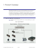
1 1 Product Overview The CyberData SIP-enabled Voice-over IP (VoIP) Paging Amplifier provides an easy method for implementing an IP-based overhead paging system for both new and legacy installations. The Amplifier provides direct drive of a standard Horn speaker and supports a line out connector for connection to an external amplifier. The interface is compatible with most SIP-based IP PBX servers that comply with the SIP RFC 3261.
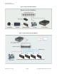
2 Product Overview Typical System Installation Figure 2. Typical Line-Out Installation Figure 3.
Product Overview 3 Product Features 1.
4 Product Overview Supported Protocols 1.3 Supported Protocols The Paging Amplifier supports: ● SIP ● Multicast ● HTTP Web-based configuration Provides an intuitive user interface for easy system configuration and verification of Paging Amplifier operations. ● DHCP Client Dynamically assigns IP addresses in addition to the option to use static addressing. ● TFTP Client Facilitates Web-based firmware upgrades of the latest Paging Amplifier capabilities.
Product Overview 5 Product Specifications 1.5 Product Specifications Category Specification Sensitivity 96dB/1W/1M S.P. Level Output With one 8-ohm speaker, up to 8 watts output With external PoE power injector (Part #010867) and one 8 ohm speaker, up to 10 watts output. With external PoE power injector (Part #010867) and two 8 ohm speakers in parallel, up to 20 watts output. Port Baud Rate 10/100 Mbps Power Requirement 802.3af compliant Protocol SIP RFC 3261 Part Number 010965 Dimensions 1.
6 Product Overview Product Specifications CyberData Corporation 930185B VoIP Paging Amplifier Operations Guide
7 2 Installing the VoIP Paging Amplifier 2.1 Parts List Table 2-1 illustrates the parts for each Paging Amplifier and includes a kit for mounting. Table 2-1.
8 Installing the VoIP Paging Amplifier Paging Amplifier Setup 2.2 Paging Amplifier Setup Set up and configure each Paging Amplifier before you mount it. CyberData delivers each Paging Amplifier with the factory default values indicated in Table 2-2: Table 2-2. Factory Default Settings Parameter Factory Default Setting IP Addressing static IP Address 192.168.3.10 Web Access Username admin Web Access Password admin Subnet Mask 255.255.255.0 Default Gateway 192.168.3.1 2.2.
Installing the VoIP Paging Amplifier 9 Paging Amplifier Setup 2.2.2 Opening the Case to Access Jumpers Use Figure 2-2 to see how to open the Paging Amplifier case to access the jumpers. Figure 2-2.
10 Installing the VoIP Paging Amplifier Paging Amplifier Setup 2.2.3 Paging Amplifier Jumpers See Figure 2-3 to identify the jumper and component locations. Figure 2-3. Jumper Locations JP9 JP8 JP7 See Table 2-3 and Table 2-4 for the jumper settings. Table 2-3. Jumper Settings—Low Power—802.3af Compliant (Default) Jumper Setting JP7 OFF -> Low Power (21V) JP8 OFF -> Low Power (21V) JP9 Position B -> Low Power Table 2-4.
Installing the VoIP Paging Amplifier 11 Paging Amplifier Setup 2.2.4 Connecting the Paging Amplifier Figure 2-4 illustrates how to connect the VoIP Paging Amplifier (PoE). 2.2.4.1 Using the Amplified Outputs Figure 2-4.
12 Installing the VoIP Paging Amplifier Paging Amplifier Setup 2.2.4.2 Using the Line Out Output Figure 2-5. Using the Line Out Output See Table 2-5 for details about the Paging Amplifier connections. Table 2-5. Paging Amplifier Connections Connection Connection Details Location Loudspeaker ● Use two binding posts for up to 0.083 inch diameter loudspeaker wire. SiP VoIP and PoE Speaker Ethernet ● Use a RJ 45 cable. SiP VoIP and PoE Speaker 2.2.4.
Installing the VoIP Paging Amplifier 13 Paging Amplifier Setup 2.2.4.4 Cabling/Wiring Using the amplified output, you may connect a loudspeaker to a Paging Amplifier with a good quality speaker cable that is limited to 25 feet in length.
14 Installing the VoIP Paging Amplifier Paging Amplifier Setup 2.2.5 Confirm Operation After connecting the Paging Amplifier to the ethernet hub, use the LEDs on the Paging Amplifier face to confirm that the Paging Amplifier is operational and linked to the network. Figure 2-7. Paging Amplifier LEDs—Power and Link Power LED (blue/green) Link LED (green/yellow) Figure 2-8.
Installing the VoIP Paging Amplifier 15 Paging Amplifier Setup 2.2.6 Confirm the IP Address, Test the Audio, and Check the Volume Table 2-6. Paging Amplifier LEDs LED Color Function Power Blue/Green The power LED is illuminated a steady blue when the power is on and blue/green when the amplifier is in the high power mode. Status Green After supplying power to the Paging Amplifier: 1.
16 Installing the VoIP Paging Amplifier Paging Amplifier Setup 2.2.7 Adjust the Volume To adjust the Paging Amplifier volume, turn the Volume dial (Figure 2-10) on the Paging Amplifier face. Note For the lineout volume, the volume is fixed and the volume control is done with the external amplifier. Figure 2-10.
Installing the VoIP Paging Amplifier 17 Configure the Paging Amplifier Parameters 2.3 Configure the Paging Amplifier Parameters To configure the Paging Amplifier online, use a standard web browser. Configure each Paging Amplifier and verify its operation before you mount it. When you are ready to mount a Paging Amplifier enclosure, refer to Appendix A, “Mounting the Amplifier” for instructions. All Paging Amplifier are initially configured with the default IP settings indicated in Table 2-7.
18 Installing the VoIP Paging Amplifier Configure the Paging Amplifier Parameters Figure 2-11. Home Page VOIP PAGING AMPLIFER 3. On the Home Page, review the setup details and navigation buttons described in Table 2-8. Table 2-8. Home Page Overview Web Page Item Description Device Name Shows the device name. Running Shows the current speaker function. Serial # Device serial number. Ethernet Address Device ethernet address.
Installing the VoIP Paging Amplifier 19 Configure the Paging Amplifier Parameters Table 2-8. Home Page Overview Web Page Item Description Link to the Upgrade Firmware web page. 2.3.2 Configure the Network Parameters 1. Click the Network Setup button to open the Network Setup page (Figure 2-12). Figure 2-12. Network Setup Page VOIP PAGING AMPLIFER 2. On the Network Setup page, enter values for the parameters indicated in Table 2-9. Table 2-9.
20 Installing the VoIP Paging Amplifier Configure the Paging Amplifier Parameters Table 2-9. Network Setup Parameters Web Page Item Description DNS Server 2* Enter the DNS Server 2 address. Click this button to save your configuration settings. Changing a parameter that has an asterisk next to it will cause a system reboot when saved. Link to the Speaker Setup page. Link to the SIP Setup page. Link to the MGROUPS Setup page. Link to the Upgrade Firmware page. Link to the Home page. 3.
Installing the VoIP Paging Amplifier 21 Configure the Paging Amplifier Parameters 2.3.3 Set up the Paging Amplifier 1. Click the Speaker Setup button to open the Speaker Setup page. Figure 2-13. Paging Amplifier Setup VOIP PAGING AMPLIFER 2. On the Paging Amplifier Setup page, enter values for the parameters indicated in Table 2-10. Table 2-10. Paging Amplifier Setup Parameters Web Page Item Description Device Name Enter a descriptive name for this device (if desired).
22 Installing the VoIP Paging Amplifier Configure the Paging Amplifier Parameters Table 2-10. Paging Amplifier Setup Parameters Web Page Item Description a RTFM Announcement Enable/Disable the speaker tone (beep) and audio associated with the RTFM switch. Click on this button to save your configuration settings. Changing a parameter that has an asterisk next to it will cause a system reboot when saved. Click on this button to do an audio test.
Installing the VoIP Paging Amplifier 23 Configure the Paging Amplifier Parameters Figure 2-14.
24 Installing the VoIP Paging Amplifier Configure the Paging Amplifier Parameters 2. On the SIP Setup page, enter values for the parameters indicated in Table 2-11. Table 2-11. SIP Setup Parameters Web Page Item Description SIP Server* Enter the SIP server represented as either a numeric IP address in dotted decimal notation or the fully qualified host name (FQHN) up to 64 characters.
Installing the VoIP Paging Amplifier 25 Set up the MGROUPS 2.4 Set up the MGROUPS MGROUPS uses multicasting to create Public Address Paging Zones. Multicasting is based on the concept of a group. Multicast addresses specify an arbitrary group of IP hosts that have joined the group and want to receive traffic sent to the group. Group members send IGMP messages to their local multicast routers, allowing the group traffic traversal from the source.
26 Installing the VoIP Paging Amplifier Set up the MGROUPS 2. On the MGROUPS Setup page, enter values for the parameters indicated in Table 2-12. Table 2-12. MGROUPS Setup Parameters Web Page Item Description Device Name Displays the device name. MG-Emergency Use MG-Emergency for the MGROUP with the highest priority. MG-(1-8) Use MG-(1-8) to assign MGROUPS 1 through 8. MG-Background Use MG-Background for the MGROUP with the lowest priority (background audio for example).
Installing the VoIP Paging Amplifier 27 Upgrade the Firmware and Reboot the Paging Amplifier 2.5 Upgrade the Firmware and Reboot the Paging Amplifier To upload the speaker firmware from your PC: 1. Set up a TFTP server. If you do not already have a TFTP server running on your network, see Chapter B, “Setting up a TFTP Server”. 2. Retrieve the latest speaker firmware from the CyberData website: http://www.cyberdata.net/support/voip/index.html 3. Unzip the speaker version file.
28 Installing the VoIP Paging Amplifier Upgrade the Firmware and Reboot the Paging Amplifier Figure 2-16. Firmware Upgrade Page VOIP PAGING AMPLIFER 7. Enter the IP address of your TFTP server into the TFTP Server IP parameter field. 8. Enter the firmware filename of the file to be uploaded into the New Filename parameter field. For example, kernel filename "201-image-spk-sip.bin". 9. Click Upload File. Note This starts the upload process.
Installing the VoIP Paging Amplifier 29 Upgrade the Firmware and Reboot the Paging Amplifier Table 2-13. Firmware Upgrade Parameters Web Page Item Description Application Shows the current application filename for partition 1 and 2. Load new firmware to Partition 1 Enter the TFTP Server IP address. New Filename Enter the new file name for the kernel or application firmware file that you are uploading. Click on this button to automatically upload the selected firmware and reboot the system.
30 Installing the VoIP Paging Amplifier Upgrade the Firmware and Reboot the Paging Amplifier Figure 2-17. Reboot System Section VOIP PAGING AMPLIFER 2. Click Reboot. A normal restart will occur as per the Status LED section of Table 2-6.
Installing the VoIP Paging Amplifier 31 Restore the Factory Default Settings 2.6 Restore the Factory Default Settings When troubleshooting configuration problems, it is sometimes convenient to restore the device to a known state. Each Paging Amplifier is delivered with factory set default values for the parameters indicated in Table 2-14. Use the RTFM switch on the Paging Amplifier face to restore these parameters to the factory default settings.
32 Installing the VoIP Paging Amplifier Restore the Factory Default Settings CyberData Corporation 930185B VoIP Paging Amplifier Operations Guide
33 Appendix A: Mounting the Amplifier A.0 Mount the Amplifier Before you mount the enclosure, make sure that you have received all of the parts for each enclosure. Refer to Table A-15. Table A-15. Wall Mounting Components (Part of the Accessory Kit) Quantity Part Name 2 Plastic Ribbed Anchors 2 #6 Sheet Metal Screws Illustration Note The Paging Amplifier was designed for indoor use.
34 Mount the Amplifier CyberData Corporation 930185B VoIP Paging Amplifier Operations Guide
35 Appendix B: Setting up a TFTP Server B.0 Set up a TFTP Server Upgrading the VoIP Paging Amplifier firmware requires a TFTP server on which you access the Web interface where you can upload the firmware files. B.0.1 In a LINUX Environment To set up a TFTP server on LINUX: 1. Create a directory dedicated to the TFTP server, and move the files to be uploaded to that directory. 2.
36 Set up a TFTP Server CyberData Corporation 930185B VoIP Paging Amplifier Operations Guide
37 Appendix C: Troubleshooting/Technical Support C.1 Frequently Asked Questions (FAQ) Go to the following URL to see CyberData’s list of frequently asked questions: http://www.cyberdata.net/support/voip/index.html C.2 Documentation The documentation for this product is released in an English language version only. You can download PDF copies of CyberData product documentation at: http://www.cyberdata.net/support/voip/index.html C.
38 Warranty C.4 Warranty CyberData warrants its product against defects in material or workmanship for a period of two years from the date of purchase. Should the product fail within the warranty period, CyberData will repair or replace the product free of charge. This warranty includes all parts and labor. If the product is out-of-warranty and fails, a flat rate repair charge of one half the product purchase price will be assessed.
39 Index Symbols E #8 sheet metal screws 33 enclosure, mounting 33 expiration time for SIP server lease 24 A F accessory kit 7 activity LED 15 address, configuration login 17 announcing an IP address 15 asterisk 20, 22 audio encodings 4 factory default settings 31 firmware upgrades 35 H home page 17 http web-based configuration 4 C changing the web access password 21 configurable parameters 18, 19, 21, 24, 28 configuration default IP settings 17 network 19 SIP 22 using Web interface 17 configurati
40 R MG-(1-8) 26 MG-Background 26 MG-Emergency 26 MGROUP Name 26 Multicast IP Address 26 mounting an amplifier 33 reboot 29, 31 registration and expiration, SIP server lease 24 remote SIP port 24 reset test function management switch 15 resetting the IP address to the default 33, 37 restoring factory default settings 31 RMA returned materials authorization 37 RTFM switch 15, 31 RTP/AVP 4 N network configuration 19 network link activity, verifying 14 Network Setup 19 S O sensitivity 5 server address, S
41 V verifying network link and activity 14 paging amplifier operations 21 power on to loudspeaker amplifer 14 W warranty 38 web access password 8, 17, 31 web access username 8, 17, 31 web configuration log in address 17 web-based paging amplifier configuration 17 weight 5 Windows, setting up a TFTP server on 35 VoIP Paging Amplifier Operations Guide 930185B CyberData Corporation
42 CyberData Corporation 930185B VoIP Paging Amplifier Operations Guide