VoIP Loudspeaker Amplifier Operations Guide (PoE) Part #010861 930106D
VoIP Loudspeaker Amplifier Operations Guide 930106D Part # 010861 COPYRIGHT NOTICE: © 2007, CyberData Corporation, ALL RIGHTS RESERVED. This manual and related materials are the copyrighted property of CyberData Corporation. No part of this manual or related materials may be reproduced or transmitted, in any form or by any means (except for internal use by licensed customers), without prior express written permission of CyberData Corporation.
Revision History Revision Date Released Description of Changes A 11/06/2006 This is the first release of this manual. B 01/16/2007 Adds Section 2.4, "Set up the MGROUPS". C 4/13/2007 Changes the Authenticate ID and password character limit from 30 to 25 in Table 2-11. D 7/20/2007 Adds Figure 2, "Public Address System—Multicast" . Adds more information about MGROUPS in Section 2.4, "Set up the MGROUPS". Adds information about the Outbound Proxy in Table 2-7.
CyberData Corporation 930106D VoIP Loudspeaker Amplifier Operations Guide
i Contents Chapter 1 Product Overview 1 1.1 Typical System Installation ...................................................................................................................1 1.2 Product Features .....................................................................................................................................2 1.3 Supported Protocols ..............................................................................................................................3 1.
ii CyberData Corporation 930106D VoIP Loudspeaker Amplifier Operations Guide
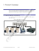
1 1 Product Overview The Voice-over-IP (VoIP) Loudspeaker Amplifier (PoE) uses a single cable to connect to existing LANs to broadcast digital audio over your public address system. The small footprint and low height makes this an ideal loudspeaker amplifier to discreetly mount almost anywhere. 1.1 Typical System Installation Figure 1 illustrates how the VoIP Loudspeaker Amplifier (PoE) is normally installed as part of a public address system. Figure 1.
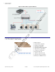
2 Product Overview Product Features Figure 2. Public Address System—Multicast CyberData VoIP Loudspeaker Amplifier Speakers Set in MGROUPS Mode 1.2 Product Features ● Multicast support ● SIP (RFC 3261) compatible ● Dual-Speed 10/100 Mbps ● Web-based configuration ● Web-based firmware upgradeable ● High-efficiency speaker driver ● PoE (Power-over-Ethernet) ● CyberData Corporation 930106D 8W output under PoE ● 16W max.
Product Overview 3 Supported Protocols 1.3 Supported Protocols The Loudspeaker Amplifier supports: ● SIP ● Multicast ● HTTP Web-based configuration Provides an intuitive user interface for easy system configuration and verification of loudspeaker amplifier operations. ● DHCP Client Dynamically assigns IP addresses in addition to the option to use static addressing. ● TFTP Client Facilitates Web-based firmware upgrades of the latest loudspeaker amplifier capabilities.
4 Product Overview Product Specifications CyberData Corporation 930106D VoIP Loudspeaker Amplifier Operations Guide
5 2 Installing the VoIP Loudspeaker Amplifier 2.1 Parts List Table 2-1 illustrates the parts for each loudspeaker amplifier and includes a kit for mounting. Table 2-1.
6 Installing the VoIP Loudspeaker Amplifier Loudspeaker Amplifier Setup 2.2 Loudspeaker Amplifier Setup Set up and configure each loudspeaker amplifier before you mount it. CyberData delivers each loudspeaker amplifier with the factory default values indicated in Table 2-2: Table 2-2. Factory Default Settings Parameter Factory Default Setting IP Addressing static IP Address 192.168.3.10 Web Access Username admin Web Access Password admin Subnet Mask 255.255.255.0 Default Gateway 192.168.3.
Installing the VoIP Loudspeaker Amplifier 7 Loudspeaker Amplifier Setup 2.2.2 Loudspeaker Amplifier Jumpers See Figure 2-2 to identify the jumper and component locations. Figure 2-2. Jumper Locations JP9 JP8 JP7 See Table 2-3 and Table 2-4 for the jumper settings. Table 2-3. Jumper Settings—Low Power—802.3af Compliant (Default) Jumper Setting JP7 OFF -> Low Power (21V) JP8 OFF -> Low Power (21V) JP9 Position B -> Low Power Table 2-4.
8 Installing the VoIP Loudspeaker Amplifier Loudspeaker Amplifier Setup 2.2.3 Connect the Loudspeaker Amplifier Figure 2-3 illustrates how to connect the VoIP Loudspeaker Amplifier (PoE). Figure 2-3.
Installing the VoIP Loudspeaker Amplifier 9 Loudspeaker Amplifier Setup See Table 2-5 for details about connecting the loudspeaker amplifier. Table 2-5. Loudspeaker Amplifier Connections Connection Connection Details Location Loudspeaker ● Use two binding posts for up to 0.083 inch diameter loudspeaker wire. VoIP paging amplifier Ethernet ● Use a RJ 45 cable. VoIP paging amplifier ● For a phase connection, use a press-down connector for 14 AWG solid copper wire.
10 Installing the VoIP Loudspeaker Amplifier Loudspeaker Amplifier Setup 2.2.4 Confirm Operation After connecting the loudspeaker amplifier to the ethernet hub, use the LEDs on the loudspeaker amplifier face to confirm that the loudspeaker amplifier is operational and linked to the network. Figure 2-5. Loudspeaker Amplifier LEDs—Power and Link Power LED (blue/green) Link LED (green/yellow) Figure 2-6. Loudspeaker Amplifier LEDs—Status and Activity Status LED (green) Activity LED (green) Table 2-6.
Installing the VoIP Loudspeaker Amplifier 11 Loudspeaker Amplifier Setup 2.2.5 Confirm the IP Address, Test the Audio, and Check the Volume When the loudspeaker amplifier is operational and linked to the network, use the Reset Test Function Management (RTFM) switch (Figure 2-7) on the loudspeaker amplifier face to announce and confirm the loudspeaker amplifier’s IP Address, test that the audio is working, and check the volume. Figure 2-7.
12 Installing the VoIP Loudspeaker Amplifier Loudspeaker Amplifier Setup 2.2.6 Adjust the Volume To adjust the loudspeaker amplifier volume, turn the Volume dial (Figure 2-8) on the loudspeaker amplifier face. Figure 2-8.
Installing the VoIP Loudspeaker Amplifier 13 Configure the Loudspeaker Amplifier Parameters 2.3 Configure the Loudspeaker Amplifier Parameters To configure the loudspeaker amplifier online, use a standard web browser. Configure each loudspeaker amplifier and verify its operation before you mount it. When you are ready to mount a loudspeaker amplifier enclosure, refer to Chapter A, “Mounting the Enclosure” for instructions.
14 Installing the VoIP Loudspeaker Amplifier Configure the Loudspeaker Amplifier Parameters Figure 2-9. Home Page 3. On the Home Page, review the setup details and navigation buttons described in Table 2-8. Table 2-8. Home Page Overview Web Page Item Description Device Name Shows the device name. Running Shows the current speaker function. Serial # Device serial number. Ethernet Address Device ethernet address. IP Addressing Shows the current IP addressing setting (DHCP or static).
Installing the VoIP Loudspeaker Amplifier 15 Configure the Loudspeaker Amplifier Parameters Table 2-8. Home Page Overview Web Page Item Description Link to the Upgrade Firmware web page.
16 Installing the VoIP Loudspeaker Amplifier Configure the Loudspeaker Amplifier Parameters 2.3.2 Configure the Network Parameters 1. Click the Network Setup button to open the Network Setup page (Figure 2-10). Figure 2-10. Network Setup Page 2. On the Network Setup page, enter values for the parameters indicated in Table 2-9. Table 2-9. Network Setup Parameters Web Page Item Description IP Addressing* Select either DHCP IP Addressing or Static IP Addressing by marking the appropriate radio button.
Installing the VoIP Loudspeaker Amplifier 17 Configure the Loudspeaker Amplifier Parameters Table 2-9. Network Setup Parameters Web Page Item Description Link to the Speaker Setup page. Link to the SIP Setup page. Link to the MGROUPS Setup page. Link to the Upgrade Firmware page. Link to the Home page. 3. After changing the parameters, click Save Settings. This updates the changed parameters and reboots the speaker if appropriate. 4. Connect the speaker to the target network. 5.
18 Installing the VoIP Loudspeaker Amplifier Configure the Loudspeaker Amplifier Parameters 2.3.3 Set up the Loudspeaker Amplifier 1. Click the Speaker Setup button to open the Speaker Setup page. See Figure 2-11 Figure 2-11. Loudspeaker Amplifier Setup 2. On the Loudspeaker Amplifier Setup page, enter values for the parameters indicated in Table 2-10. Table 2-10. Loudspeaker Amplifier Setup Parameters Web Page Item Description Device Name Enter a descriptive name for this device (if desired).
Installing the VoIP Loudspeaker Amplifier 19 Configure the Loudspeaker Amplifier Parameters Table 2-10. Loudspeaker Amplifier Setup Parameters Web Page Item RTFM Announcement Description a Enable/Disable the speaker tone (beep) and audio associated with the RTFM switch. Click on this button to save your configuration settings. Changing a parameter that has an asterisk next to it will cause a system reboot when saved. Click on this button to do an audio test.
20 Installing the VoIP Loudspeaker Amplifier Configure the Loudspeaker Amplifier Parameters Figure 2-12.
Installing the VoIP Loudspeaker Amplifier 21 Configure the Loudspeaker Amplifier Parameters 2. On the SIP Setup page, enter values for the parameters indicated in Table 2-11. Table 2-11. SIP Setup Parameters Web Page Item Description SIP Server* Enter the SIP server represented as either a numeric IP address in dotted decimal notation or the fully qualified host name (FQHN) up to 64 characters.
22 Installing the VoIP Loudspeaker Amplifier Set up the MGROUPS 2.4 Set up the MGROUPS MGROUPS uses multicasting to create Public Address Paging Zones. Multicasting is based on the concept of a group. Multicast addresses specify an arbitrary group of IP hosts that have joined the group and want to receive traffic sent to the group. Group members send IGMP messages to their local multicast routers, allowing the group traffic traversal from the source.
Installing the VoIP Loudspeaker Amplifier 23 Set up the MGROUPS 2. On the MGROUPS Setup page, enter values for the parameters indicated in Table 2-12. Table 2-12. MGROUPS Setup Parameters Web Page Item Description Device Name Displays the device name. MG-Emergency Use MG-Emergency for the MGROUP with the highest priority. MG-(1-8) Use MG-(1-8) to assign MGROUPS 1 through 8. MG-Background Use MG-Background for the MGROUP with the lowest priority (background audio for example).
24 Installing the VoIP Loudspeaker Amplifier Upgrade the Firmware and Reboot the Loudspeaker Amplifier 2.5 Upgrade the Firmware and Reboot the Loudspeaker Amplifier To upload the speaker firmware from your PC: 1. Set up a TFTP server. If you do not already have a TFTP server running on your network, see Chapter B, “Setting up a TFTP Server”. 2. Retrieve the latest speaker firmware from the CyberData website: www.CyberData.net/support/voip 3. Unzip the speaker version file.
Installing the VoIP Loudspeaker Amplifier 25 Upgrade the Firmware and Reboot the Loudspeaker Amplifier Figure 2-14. Firmware Upgrade Page 7. Enter the IP address of your TFTP server into the TFTP Server IP parameter field. 8. Enter the firmware filename of the file to be uploaded into the New Filename parameter field. For example, kernel filename "201-image-spk-sip.bin". 9. Click Upload File. Note This starts the upload process.
26 Installing the VoIP Loudspeaker Amplifier Upgrade the Firmware and Reboot the Loudspeaker Amplifier Table 2-13. Firmware Upgrade Parameters Web Page Item Description Application Shows the current application filename for partition 1 and 2. Load new firmware to Partition 1 Enter the TFTP Server IP address. New Filename Enter the new file name for the kernel or application firmware file that you are uploading.
Installing the VoIP Loudspeaker Amplifier 27 Upgrade the Firmware and Reboot the Loudspeaker Amplifier Figure 2-15. Reboot System Section 2. Click Reboot. A normal restart will occur as per the Status LED section of Table 2-6.
28 Installing the VoIP Loudspeaker Amplifier Restore the Factory Default Settings 2.6 Restore the Factory Default Settings When troubleshooting configuration problems, it is sometimes convenient to restore the device to a known state. Each loudspeaker amplifier is delivered with factory set default values for the parameters indicated in Table 2-14. Use the RTFM switch on the loudspeaker amplifier face to restore these parameters to the factory default settings.
29 Appendix A: Mounting the Enclosure A.0 Mount the Enclosure Before you mount the enclosure, make sure that you have received all of the parts for each enclosure. Refer to Table A-15. Table A-15. Wall Mounting Components (Part of the Accessory Kit) Quantity Part Name 3 #8 Sheet Metal Screws Note Illustration The loudspeaker amplifier was designed for indoor use.
30 Mount the Enclosure Figure A-1.
31 Appendix B: Setting up a TFTP Server B.0 Set up a TFTP Server Upgrading the VoIP Loudspeaker Amplifier firmware requires a TFTP server on which you access the Web interface where you can upload the firmware files. B.0.1 In a LINUX Environment To set up a TFTP server on LINUX: 1. Create a directory dedicated to the TFTP server, and move the files to be uploaded to that directory. 2.
32 Set up a TFTP Server CyberData Corporation 930106D VoIP Loudspeaker Amplifier Operations Guide
33 Appendix C: Troubleshooting/Technical Support C.1 Frequently Asked Questions (FAQ) Go to the following URL to see CyberData’s list of frequently asked questions: http://www.CyberData.net/support/voip C.2 Documentation The documentation for this product is released in an English language version only. You can download PDF copies of CyberData product documentation at: www.CyberData.net—>Support—>Drivers, Utilities & Manuals—>VoIP Products C.
34 Warranty C.4 Warranty CyberData warrants its product against defects in material or workmanship for a period of two years from the date of purchase. Should the product fail within the warranty period, CyberData will repair or replace the product free of charge. This warranty includes all parts and labor. If the product is out-of-warranty and fails, a flat rate repair charge of one half the product purchase price will be assessed.
35 Index DHCP Client 3 DHCP IP addressing 16 dimensions 3 DNS server 16 Symbols #8 sheet metal screws 29 Numerics E 3 x #8 x 1-1/4” truss head screws 5 enclosure, mounting 29 expiration time for SIP server lease 21 A F accessory kit 5 activity LED 10 address, configuration login 13 announcing a loudspeaker amplifier’s IP address 11 asterisk 16, 19 audio encodings 3 factory default settings 28 firmware upgrades 31 H home page 13 http web-based configuration 3 C changing the web access password 18
36 loudspeaker amplifer setup 18 loudspeaker amplifier configuration default IP settings 13 loudspeaker amplifier configuration page configurable parameters 14, 16, 21, 25 loudspeaker amplifier operations, verifying 18 loudspeaker, cabling/wiring 9 loudspeaker, type 9 product configuring 13 mounting 29 parts list 5 product features 2 product overview product features 2 product specifications 3 supported protocols 3 supported SIP servers 3 typical system installation 1 product specifications 3 protocols su
37 U unregister, from SIP server 21 user ID for SIP server login 21 user ID, SIP 21 username changing for web configuration access 18 default for web configuration access 13 restoring the default 6, 13, 28 V verifying loudspeaker amplifier operations 18 network link and activity 10 power on to loudspeaker amplifer 10 W warranty 34 web access password 6, 13, 28 web access username 6, 13, 28 web configuration log in address 13 web-based loudspeaker amplifier configuration 13 weight 3 Windows, setting up a
38 CyberData Corporation 930106D VoIP Loudspeaker Amplifier Operations Guide