4-Port PoweredUSB 2.
4-Port PoweredUSB 2.0 Hub Operations Guide 930103D Part # 010807 COPYRIGHT NOTICE: © 2007, CyberData Corporation, ALL RIGHTS RESERVED. This manual and related materials are the copyrighted property of CyberData Corporation. No part of this manual or related materials may be reproduced or transmitted, in any form or by any means (except for internal use by licensed customers), without prior express written permission of CyberData Corporation.
Contents iii Contents Chapter 1 Product Overview 1 Chapter 2 Installing and Using the 4-Port PoweredUSB Hub 3 2.1 Product Components List .....................................................................................................................3 2.2 Product Compatibility ...........................................................................................................................4 2.3 Installation ..................................................................................
iv Contents CyberData Corporation 930103D Operations Guide
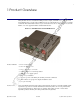
1 1 Product Overview The CyberData 4-Port PoweredUSB 2.0 Hub provides a simple, affordable way to add up to four PoweredUSB ports to your PC. These additional ports are controlled by the PC’s Standby and Wake commands. This add-on Hub makes it easy to connect the PC to devices that require more than the 500mA of +5 volts supplied with the standard USB interface. Figure 1-1. CyberData 4-Port PoweredUSB 2.
2 Product Overview Documentation note The documentation for this product is released in an English language version only.
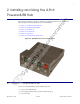
3 2 Installing and Using the 4-Port PoweredUSB Hub This chapter provides the instructions, illustrations, and background information you need to install, and begin working with the 4-Port PoweredUSB Hub. ● Section 2.1, "Product Components List" ● Section 2.2, "Product Compatibility" ● Section 2.3, "Installation" ● Section 2.4, "Connections" ● Section 2.5, "Operation" ● Section 2.6, "Port Electrical Specifications" Figure 2-2. CyberData 4-Port PoweredUSB 2.0 Hub 2.
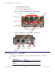
4 Installing and Using the 4-Port PoweredUSB Hub • (1) Short USB 2.0 Hi-Speed host cable • (1) Host USB cable strain relief clamp • (1) 4-Port PoweredUSB Hub Operations Guide Figure 2-3. CyberData 4-Port PoweredUSB 2.0 Hub—Front View Port Power LED +12V PoweredUSB Ports Hub Power LED Link LED Port 1 Status LED Lower portion of PoweredUSB Port connectors are Standard USB 2.0 Hi-Speed “A” ports Figure 2-4. CyberData 4-Port PoweredUSB 2.0 Hub—Back View +24V for up to 2.
Installing and Using the 4-Port PoweredUSB Hub 5 2.3 Installation The 4-Port PoweredUSB Hub is a tabletop unit with mounting feet that sit on a flat surface. 2.4 Connections This following topics provide illustrations and information on connecting the 4-Port PoweredUSB Hub to power supplies, the host, and peripheral devices. Operations Guide ● Section 2.4.1, "Power Supply" ● Section 2.4.2, "Host Connector" ● Section 2.4.3, "PoweredUSB Connections" ● Section 2.4.
6 Installing and Using the 4-Port PoweredUSB Hub 2.4.1 Power Supply The PoweredUSB specification requires supplying +24V at 2.3A and +12V at 1.5A to each voltage designated port. These requirements are met only if the power supply has sufficient wattage for this amount of power. The Epson PS180 brick and Dell printer power supply are examples of lower-cost alternate power supplies that can be used with this Hub and peripherals requiring less power.
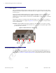
Installing and Using the 4-Port PoweredUSB Hub 7 Figure 2-6. Host connector with strain relief 2.4.3 PoweredUSB Connections The PoweredUSB connections are standard USB “A” connectors with four extra pins to supply higher voltages. See Figure 2-8 for an illustration. The lower portion of the “A” connector side on this product can be used alone, without the locking PoweredUSB connector. 2.4.
8 Installing and Using the 4-Port PoweredUSB Hub Figure 2-8.
Installing and Using the 4-Port PoweredUSB Hub 9 2.4.5 Peripherals Connections to the 4-Port PoweredUSB Hub This figure illustrates the cable routing from the 4-Port PoweredUSB Hub to the Dell Retail Integrator. Figure 2-9.
10 Installing and Using the 4-Port PoweredUSB Hub 2.4.6 Peripheral Cable Connection Options Figures 10 through 16 provide examples of peripheral cable combinations and connection options for the 4-Port PoweredUSB Hub. The following table provides details about the CyberData PoweredUSB Cables displayed in these figures. PoweredUSB cable sources Custom cables of different lengths and colors can be purchased from CyberData as follows: ● Via email: sales@cyberdata.
Installing and Using the 4-Port PoweredUSB Hub 11 Figure 2-11. Cables; +12V PoweredUSB to +12V Power Jack and RS-232 to RS-232 Figure 2-12.
12 Installing and Using the 4-Port PoweredUSB Hub Figure 2-13. “Y” Cable, +24V PoweredUSB to 3-Pin Power Mini-DIN and USB “B” Connectors Figure 2-14. RS232 to USB Converter “Y” Cable +12V (PC Enumerates this device as an RS-232 COM port) Figure 2-15.
Installing and Using the 4-Port PoweredUSB Hub 13 Figure 2-16. RS232 to USB Converter “Y” Cable +24V 2.5 Operation The 4-Port PoweredUSB Hub is a standard USB Hub that complies with the USB 2.0 specification, and adds PoweredUSB ports. When connected to a Host, it is enumerated as a Generic USB Hub. This Hub also meets the PoweredUSB .08g specification. For more information about this specification, go to www.poweredusb.org. POS peripheral caveat According to the USB 2.
14 Installing and Using the 4-Port PoweredUSB Hub 2.6 Port Electrical Specifications The 4-Port PoweredUSB Hub adheres to the USB 2.0 electrical specifications as follows: Standard USB lower A supply Each lower portion of the PoweredUSB port provides +5V @ 500mA. If more than 500mA are drawn from a port, that port goes into USB over current, the +5 volts is turned off, and the condition is reported to the host according to USB 2.0 specifications.
15 Appendix A: Regulatory and Safety Information A.1 Regulatory standards FCC Statement: This equipment has been tested and found to comply with the limits for a Class A digital device, pursuant to Part 15 of the FCC Rules. These limits are designed to provide reasonable protection against harmful interference when the equipment is operated in a commercial environment.
16 CyberData Corporation • EN 61000-4-4: 1995 • EN 61000-4-5: 1995 • EN 61000-4-6: 1996 • EN 61000-4-8: 1993 • EN 61000-4-11: 1995 930103D Operations Guide
17 Appendix B: Setting up the Hub on Windows XP For connecting the 4-Port PoweredUSB Hub to a PC running the Windows XP operating system, keep in mind: 1. Microsoft XP Service Pack 1 or higher must be installed. 2. When connecting the Hub for the first time, it is important to perform the enumeration correctly. A Microsoft XP Service Pack issue does not enumerate and recognize a Hub when no devices are attached to it.
18 CyberData Corporation 930103D Operations Guide
19 Appendix C: Troubleshooting/Technical Support C.1 Frequently Asked Questions (FAQ) Go to the following URL to see CyberData’s list of frequently asked questions: http://www.cyberdata.net/support/pusb/4portpusb.html C.2 Documentation The documentation for this product is released in an English language version only. You can download PDF copies of CyberData product documentation at: www.CyberData.net—>Support—>Drivers, Utilities & Manuals—>PoweredUSB, 4 Port Hub C.
20 CyberData Corporation 2555 Garden Road Monterey, CA 93940 Attention: RMA "your RMA number" C.4 Warranty CyberData warrants its product against defects in material or workmanship for a period of two years from the date of purchase. Should the product fail within the warranty period, CyberData will repair or replace the product free of charge. This warranty includes all parts and labor.
21 Index A H accessory kit 3, 6 active over current circuits.
22 R regulatory standards 15 resetting the IP address to the default 19 RMA returned materials authorization 19 S short circuit protection 1 T technical support, contact information 19 U USB 2.