The IP Endpoint Company 4-Port PoweredUSB 2.
4-Port PoweredUSB 2.0 Hub Operations Guide 930103G Part # 010807 COPYRIGHT NOTICE: © 2011, CyberData Corporation, ALL RIGHTS RESERVED. This manual and related materials are the copyrighted property of CyberData Corporation. No part of this manual or related materials may be reproduced or transmitted, in any form or by any means (except for internal use by licensed customers), without prior express written permission of CyberData Corporation.
Revision Information Revision 930103G, which was released on August 31, 2011, has the following changes: • Updates Section Appendix C:, "Troubleshooting/Technical Support".
Important Safety Instructions 1. Read these instructions. 2. Keep these instructions. 3. Heed all warnings. 4. Follow all instructions. 5. Do not use this apparatus near water. 6. Clean only with dry cloth. 7. Do not block any ventilation openings. Install in accordance with the manufacturer’s instructions. 8. Do not install near any heat sources such as radiators, heat registers, stoves, or other apparatus (including amplifiers) that produce heat. 9.
Pictorial Alert Icons General Alert This pictoral alert indicates a potentially hazardous situation. This alert will be followed by a hazard level heading and more specific information about the hazard. GENERAL ALERT Ground This pictoral alert indicates the Earth grounding connection point. Hazard Levels Danger: Indicates an imminently hazardous situation which, if not avoided, will result in death or serious injury. This is limited to the most extreme situations.
i Contents Chapter 1 Product Overview 1 1.1 Product features .....................................................................................................................................1 1.2 License note .............................................................................................................................................2 1.3 Documentation note ..............................................................................................................................2 1.
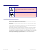
1 1 Product Overview The 4-Port PoweredUSB Hub provides a simple, affordable way to add up to four PoweredUSB ports to your PC. These additional ports are controlled by the PC’s Standby and Wake commands. This add-on Hub makes it easy to connect the PC to devices that require more than the 500mA of +5 volts supplied with the standard USB interface. Figure 1-1. CyberData 4-Port PoweredUSB 2.0 Hub 1.1 Product features Operations Guide ● 4 PoweredUSB ports ● One +24 volt up to 2.
Product Overview 2 License note 1.2 License note The PoweredUSB controller board contains certain technology that is covered by an IBM ® patent. CyberData Corporation is licensed with IBM to manufacture, and to sell or lease products that incorporate this technology. This license also permits other entities to resell or release these Cyberdata products after they have been purchased from CyberData. 1.3 Documentation note The documentation for this product is released in an English language version only.
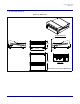
Product Overview 3 Dimensions 1.4 Dimensions Figure 1-2. Dimensions Perspective View A 1.78 [45.3] 3.71 [94.3] A 4.34 [110.
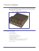
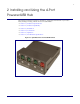
4 2 Installing and Using the 4-Port PoweredUSB Hub This chapter provides the instructions, illustrations, and background information you need to install, and begin working with the 4-Port PoweredUSB Hub. ● Section 2.1, "Product Components List" ● Section 2.2, "Product Compatibility" ● Section 2.3, "Installation" ● Section 2.4, "Connections" ● Section 2.5, "Operation" ● Section 2.6, "Port Electrical Specifications" Figure 2-3. CyberData 4-Port PoweredUSB 2.
Installing and Using the 4-Port PoweredUSB Hub 5 Product Components List 2.1 Product Components List The 4-Port PoweredUSB 2.0 Hub package includes these parts: ● (1) 4-Port PoweredUSB Hub ● Power Supply, 24VDC, Desk-top, 4-Pin Hosiden style plug ● (1) Accessory Kit • (1) Short USB 2.0 Hi-Speed host cable • (1) Host USB cable strain relief clamp • (1) 4-Port PoweredUSB 2.0 Hub Operations Guide Figure 2-4. CyberData 4-Port PoweredUSB 2.
Installing and Using the 4-Port PoweredUSB Hub 6 Product Compatibility 2.2 Product Compatibility The 4-Port PoweredUSB Hub is compatible with the following operating systems and USB standards. Table 2-1. Operating Systems Operating systems USB Windows 2000 and XP 2.0 Standard LINUX PoweredUSB 0.8g Mac OS-X 2.3 Installation The 4-Port PoweredUSB Hub is a tabletop unit with mounting feet that sit on a flat surface.
Installing and Using the 4-Port PoweredUSB Hub 7 Connections 2.4 Connections This following topics provide illustrations and information on connecting the 4-Port PoweredUSB Hub to power supplies, the host, and peripheral devices. ● Section 2.4.1, "Power Supply" ● Section 2.4.2, "Host Connector" ● Section 2.4.3, "PoweredUSB Connections" ● Section 2.4.4, "Connector Color Keys" ● Section 2.4.5, "Peripherals Connections to the 4-Port PoweredUSB Hub" ● Section 2.4.
Installing and Using the 4-Port PoweredUSB Hub 8 Connections 2.4.2 Host Connector The connection to the host computer is achieved via a standard USB 2.0 certified Hi-Speed “A” to “B” cable that is included in the Accessory Kit, or with any equivalent USB 2.0 certified Hi-Speed cable. Refer to the Section 2.1, "Product Components List" for information about the Accessory Kit. Figure 2-7. Host connector with strain relief 2.4.
Installing and Using the 4-Port PoweredUSB Hub 9 Connections 2.4.4 Connector Color Keys The PoweredUSB connectors are color keyed so that only the correct voltage cables can be installed. Figure 2-8. Color-Coding for Connectors Teal Red 12 Volt Keyed 1.5A each Ports 1,2, and 3 24 Volt Keyed 2.3A Ports 4 Figure 2-9.
Installing and Using the 4-Port PoweredUSB Hub 10 Connections 2.4.5 Peripherals Connections to the 4-Port PoweredUSB Hub This figure illustrates the cable routing from the 4-Port PoweredUSB Hub to the Dell Retail Integrator. Figure 2-10.
Installing and Using the 4-Port PoweredUSB Hub 11 Connections 2.4.6 Peripheral Cable Connection Options Figures 10 through 16 provide examples of peripheral cable combinations and connection options for the 4-Port PoweredUSB Hub. The following table provides details about the CyberData PoweredUSB Cables displayed in these figures. PoweredUSB cable Custom cables of different lengths and colors can be purchased from CyberData as follows: sources ● Via email: sales@cyberdata.
Installing and Using the 4-Port PoweredUSB Hub 12 Connections Figure 2-12. Cables; +12V PoweredUSB to +12V Power Jack and RS-232 to RS-232 Figure 2-13.
Installing and Using the 4-Port PoweredUSB Hub 13 Connections Figure 2-14. “Y” Cable, +24V PoweredUSB to 3-Pin Power Mini-DIN and USB “B” Connectors Figure 2-15. RS232 to USB Converter “Y” Cable +12V (PC Enumerates this device as an RS-232 COM port) Figure 2-16.
Installing and Using the 4-Port PoweredUSB Hub 14 Operation Figure 2-17. RS232 to USB Converter “Y” Cable +24V 2.5 Operation The 4-Port PoweredUSB Hub is a standard USB Hub that complies with the USB 2.0 specification, and adds PoweredUSB ports. When connected to a Host, it is enumerated as a Generic USB Hub. This Hub also meets the PoweredUSB .08g specification. For more information about this specification, go to www.poweredusb.org. 2.5.1 POS Peripheral Caveat According to the USB 2.
Installing and Using the 4-Port PoweredUSB Hub 15 Port Electrical Specifications 2.6 Port Electrical Specifications The 4-Port PoweredUSB Hub adheres to the USB 2.0 electrical specifications as follows: 2.6.1 Standard USB lower A supply Each lower portion of the PoweredUSB port provides +5V @ 500mA. If more than 500mA are drawn from a port, that port goes into USB over current, the +5 volts is turned off, and the condition is reported to the host according to USB 2.0 specifications. 2.6.
16 Appendix A: Regulatory and Safety Information Regulatory standards Safety standards EMC FCC Statement: This equipment has been tested and found to comply with the limits for a Class A digital device, pursuant to Part 15 of the FCC Rules. These limits are designed to provide reasonable protection against harmful interference when the equipment is operated in a commercial environment.
17 Appendix B: Setting up the Hub on Windows XP For connecting the 4-Port PoweredUSB Hub to a PC running the Windows XP operating system, keep in mind: 1. Microsoft XP Service Pack 1 or higher must be installed. 2. When connecting the Hub for the first time, it is important to perform the enumeration correctly. A Microsoft XP Service Pack issue does not enumerate and recognize a Hub when no devices are attached to it.
18 Appendix C: Troubleshooting/Technical Support C.1 Frequently Asked Questions (FAQ) To see a list of frequently asked questions for your product, go to the following website: http://www.cyberdata.net/products/retail/pusb/pusb4porthub/faqs.html C.2 Documentation The documentation for this product is released in an English language version only. You can download PDF copies of CyberData product documentation by going to the following website: http://www.cyberdata.net/products/retail/pusb/pusb4porthub/docs.
19 Contact Information C.3 Contact Information Contact CyberData Corporation 3 Justin Court Monterey, CA 93940 USA www.CyberData.net Phone: 800-CYBERDATA (800-292-3732) Fax: 831-373-4193 Sales Sales 831-373-2601 Extension 334 Technical Support The fastest way to get technical support for your VoIP product is to submit a VoIP Technical Support form at the following website: http://www.cyberdata.net/support/contactsupportvoip.
20 Warranty C.4 Warranty CyberData warrants its product against defects in material or workmanship for a period of two years from the date of purchase. Should the product fail within the warranty period, CyberData will repair or replace the product free of charge. This warranty includes all parts and labor. Should the product fail out-of-warranty, a flat rate repair charge of one half of the purchase price of the product will be assessed.
21 Warranty C.4.4 Return and Restocking Policy For our authorized distributors and resellers, please refer to your CyberData Service Agreement for information on our return guidelines and procedures. For End Users, please contact the company that you purchased your equipment from for their return policy. C.4.5 Warranty and RMA Returns Page The most recent warranty and RMA information is available at the CyberData Warranty and RMA Returns Page at the following web address: http://www.cyberdata.
22 Index A H accessory kit 5, 8 active over current circuits.
23 product compatibility 6 R regulatory standards 16 return and restocking policy 21 RMA returned materials authorization 19 RMA status 19 S safety instructions iv sales 19 service 19 short circuit protection 1 Spare in the Air Policy 20 T tech support 19 technical support, contact information 19 U USB 2.