S1 MK2 User’s Manual (Guide/Handbook)
Table of contents page Certification.............................................................................................. 1 Warranty and Assistance........................................................................ 1 Limitation of warranty............................................................................. 1 Before using this Synthesizer................................................................ 2 Checking Accessories..............................................................
Reset Message Received................................................................. CV Gate/Trigg Configuration............................................................. Setting for CV Outputs...................................................................... Setting Parameters........................................................................... Routing the CV Outputs.................................................................... Parameter Values, Table 1................................
CERTIFICATION Cwejman certifies that this instrument was thoroughly tested and inspected and found to meet its published specifications when it was shipped from the factory. WARRANTY AND ASSISTANCE All Cwejman products are warranted against defects in materials and workmanship. This warranty applies for 1 years from the date of delivery. We will repair or replace products, which prove to be defective during the warranty period provided they are returned to Cwejman.
Before Using this Synthesizer Checking Accessories Upon receipt of this instrument, run the checks shown below: Run visual checks against any and all damages or imperfections. Check the quantity and rating of standard accessories to assure their conformance with the table below. Should there be any flaw, or damage, or missing or insufficient materials, contact the dealer or the sales and support office. Power cable Interconnection cables, 3.
Safety Symbols The WARNING sign denotes a hazard. It calls attention to a procedure, practice or the like which, if not correctly performed or adhered to, could result in injury or loss of life. Do not proceed beyond a WARNING sign until the indicated conditions are fully understood and met. The CAUTION sign denotes a hazard.
Introduction The S1 is a semi-modular, analogue monophonic synthesizer. It is easy to get started with since it is prepatched for optimal use of its sound producing possibilities and eliminates the need for external connections between modules during use. Each module can be disconnected and used separately, e.g. to control or be controlled by other instruments. This flexibility enables and simplifies experimentation with creation and reproduction of sound.
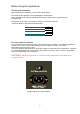
CALIBRATION OSC1, OSC2, OSC3, SCALE; 1 Volt/octave OSC1, OSC2, OSC3, RANGE; ’RANGE’ octave steps MASTER, SCALE; general scale sensitivity calibration MASTER, ANALOG CV INPUT; 1 Volt/octave MAINS INLET 115/230 V SELECTOR Power cord inlet INSTRUMENT OUTPUTS BALANCED, 16 dBVmax @ 600 ohm (rear panel) SINGLE ENDED, 10 dBVmax (front and rear panel) Switch for mains voltage selection GETTING STARTED We guess that the first of all, you want to hear how the S1 sounds.
Now begin to experiment: - Turn the FILTER MIX knob in the MASTER AMP section in position LPF or MMF to hear signals of all oscillators. - Change the waveforms and tunings of the oscillators. - Change the setting of the LPF- and MMF sections (CUTOFF, Q-PEAK, POLE, MODE) and move the FILTER MIX knob in the MASTER AMP section. See how timbres are changing? - Turn up the CUTOFF MODULATION (CM) knobs and experiment with the ENVELOPE GENERATOR settings to add dynamic timbre changes to the sound.
This allows you to individually modulate the frequency of each of oscillator and the master controller just by moving the FM LEVEL knobs in the oscillator section. The same aplied to the MODULATION LEVEL knob in the MASTER CONTROLLER section. The MODULATION INPUT sockets breaks these pre-patched signals and allow you to redirect any other signal to frequency control of the oscillators and the master tuning.
MASTER GLIDE TIME CONTROLLER 1 millisecond to 10 seconds MASTER TRANSPOSE 6 octaves in 1 octave steps MASTER TUNING ± 3 semitones MASTER MODULATION LEVEL pre-patched to LFO ENVELOPE GENERATOR 1 SELECTOR TRIGGER 1, main MIDI channel TRIGGER 2, main MIDI channel + 1 LOWPASS FILTER MASTER CV TRACKING 0 to 2 octaves/Volt MASTER CV1 CONTROL ON/OFF SELECTOR for OSCILLATORS 1, 2, 3 MULTI-MODE FILTER MASTER CV TRACKING 0 to 2 octaves/Volt ENVELOPE GENERATOR 2 SELECTOR GATE 1, main MIDI channel GATE 2, main MI
OSCILLATORS The Oscillators (OSC1-3) are the main sound sources of the instrument. They are identical, except to their pre-patched frequency modulation sources and the fact that OSC1 can be switched to LFO mode. Oscillators are equipped with seven waveforms, sync and different frequency and pulse width modulation routes. Given that, the oscillators offer a great flexibility in wave shaping process. The oscillator's frequency is controlled by RANGE, TUNE, MASTER CONTROLLER and FM LEVEL.
OSCILLATOR 1 RANGE AUDIO mode RANGE LF mode TUNE PULSE WIDTH Waveforms 0 (C2) to 6 (C8) in 1 octave steps. 8 seconds to 120 milliseconds. ± 6 semitones. 5% to 95%. Sine, Triangle, Saw, Saw+Triangle, Triangle + Pulse, Saw+Pulse, Pulse: ± 5 Volts. OSCILLATOR 2 RANGE TUNE PULSE WIDTH Waveforms SYNC 0 (C2) to 6 (C8) in 1 octave steps. ± 6 semitones. 5% to 95%. Sine, Triangle, Saw, Saw+Triangle, Triangle + Pulse, Saw+Pulse, Pulse: ± 5 Volts. Hard synchronized to Oscillator 1.
CV, LEVEL CV, PWM Amplitude modulation input, ± 5 Volts wave @ 5Volts input CV. Pulse width modulation input, 5% pulse width/ 1Volt input CV. Mixer This is a two input / two output DC-coupled mixer with input level controls. The inputs are pre-patched to the LFO triangle wave and to the ENVELOPE GENERATOR 1, but can be coupled to any other source. The outputs deliver the sum of the attenuated input signals and its inverted signal (sum+ and sum-).
Ring Modulator A ring modulator is a classic audio effect device and due to the non harmonic character of the output signal, very useful to create metallic timbres such as bells, sweeping whistles and percussive sounds and tremolo effects (modulated by low periodic signal like a LFO). Two input signals are needed and pre-patched to OSC 2 and 3 sine wave outputs. Using the EXT INPUT sockets, any other signal (internal- or external signal source) can be routed directly into the ring modulator.
LFO, Low Frequency Oscillator The LFO provides a sub-audio signal for modulation purposes. It is used to achieve periodic modulations like sweeps, vibrato effects or arpeggios. RATE determines the frequency of the LFO and is indicated by the LED WAVEFORM SELECTOR provides seven different waveforms.
Low Pass Filter Audio Mixer Audio mixer for oscillator 1, 2, 3, ring modulator and pre-patched multi mode filters output. The output signals of the three oscillators, the ring modulator and the output signal of the multimode filter has individual levels into the lowpass filter input. The red labelling indicates the saturation level of the filter's input stage when one source is used. Using more than one signal source, leads to earlier saturation.
Filters The most important sound shaping device of every substractive synthesizer is the filter. It cuts off specific and adjustable frequency ranges and thus overtones, which can result in drastic sonic changes of the filtered audio material. In the following, you will find a brief description of a filter in general, more detailed and technical information can be found on page 38 of this manual.
FUNCTIONS CUTOFF controls the filters cutoff- (or corner-) frequency. POLE selects between 4 pole low pass, quasi band pass (that sounds different than the "true" bandpass of the MMF) and 6 pole low pass. Q-PEAK determines the boost of the corner frequency. From "9" on, the filter starts self-oscillating. To create useful and interesting sounds, the cutoff parameter has to be controlled dynamically.
CUTOFF (CORNER FREQUENCY) TUNING; 16 Hz to 16 kHz 4 POLE / BANDPASS 6 POLE SELECTOR CORNER PEAK CONTROL FLAT to OSCILLATION SOURCE SELECTOR POSITIVE/ NEGATIVE GOING ENVELOPE GENERATOR 1 CORNER FREQUENCY MODULATION by ENVELOPE GENERATOR 1 SOURCE SELECTOR POSITIVE/ NEGATIVE GOING ENVELOPE GENERATOR 2 CORNER FREQUENCY MODULATION by ENVELOPE GENERATOR 2 CORNER FREQUENCY MODULATION by OSCILLATOR1 TRIANGLE/ LFO SOURCE SELECTOR OSCILLATOR 1 TRIANGLE/ LFO EXTERNAL AUDIO INPUT pre-patched to MULTI-MODE FILT
MULTI MODE FILTER The MMF is the most flexible filter found in any monophonic synthesizer.
CUTOFF FREQUENCY TUNING 16 Hz to 16 kHz 2-4-6 POLE SELECTOR LOW-PASS/ HIGH-PASS/ BAND-PASS MODE SELECTOR CORNER PEAK CONTROL FLAT to OSCILLATION SOURCE SELECTOR POSITIVE/ NEGATIVE GOING ENVELOPE GENERATOR 1 CUTOFF FREQUENCY MODULATION by ENVELOPE GENERATOR 1 SOURCE SELECTOR POSITIVE/ NEGATIVE GOING ENVELOPE GENERATOR 2 CUTOFF FREQUENCY MODULATION by ENVELOPE GENERATOR 2 SOURCE SELECTOR OSCILLATOR 1 TRIANGLE/ LFO CUTOFF FREQUENCY MODULATION by OSCILLATOR1 TRIANGLE/ LFO EXTERNAL AUDIO INPUT pre-patc
Envelope Generators The envelope generators provide control voltages (CV's) that can be used to dynamicy change of parameters, such as; frequency, amplitude, pulse width, cutoff. The most common use is in connection with a filter and a voltage controlled amplifier in order to achieve dynamic timbre- and level-changes. Thus the envelopes of the S1 are internally connected to the oscillators, filters and the amp, but can be routed elsewhere via the patch-panel. Both envelope generators are identical.
ATTACK TIME DECAY TIME SUSTAIN LEVEL RELEASE TIME DELAY TIME CV, ATTACK CV, DECAY CV, SUSTAIN CV, RELEASE CV, DELAY CV, LEVEL OUTPUTS 0.5 milliseconds to 20 seconds 0.5 milliseconds to 20 seconds 0 to 5 Volts 0.5 milliseconds to 20 seconds 1 millisecond to 10 seconds 0.5 milliseconds to 20 seconds @ 0 to 5 Volts CV 0.5 milliseconds to 20 seconds @ 0 to 5 Volts CV 0 to 5 Volts @ 0 to 5 Volts CV 0.
LOW-PASS and MULTI-MODE FILTER AUDIO MIXER OVERDRIVE CONTROLLER CLEAN (0) to SATURATED (10) AUDIO OUTPUT LEVEL ENVELOPE GENERATOR 1 & 2 AMPLITUDE CONTROL MIXER AMPLITUDE CONTROL MODE LINEAR 20%/Volt LOG 16 dB/Volt EXTERNAL AUDIO INPUT pre-patched to LOW-PASS FILTER OUTPUT MASTER AMPLIFIER AUDIO OUTPUT VELOCITY CONTROL SWITCH EXTERNAL VELOCITY CONTROL and AMP MODULATION pre-patched to CV2 AUDIO, FILTER MIX AUDIO, OVERDRIVE AUDIO, EXT INPUT AUDIO, OUTPUT AM, ENVELOPE MODE AM, ENVELOPE MODE AM, EXT VEL
REAR PANEL 23
MIDI INTERFACE MIDI IN (and programming), MIDI OUT (only program verification) and MIDI THRU CV1 CV2 CV3 MIDI OUTPUTS MIDI CHANNEL ANALOG INPUTS CALIBRATION MAINS INLET 115/230 V SELECTOR INSTRUMENT OUTPUTS Fixed: main tune, 0 to 10 Volts (10 octaves) Factory preset: Note on Velocity, 0 to 5 Volts Factory preset: Control Change #05, Modulation Wheel, 0 Volt ± 5 Volts CV4 Factory preset: Channel After Touch, 0 to 5 Volts MASTER CV + Glide & Pitch Bend control GATE1 +15 Volts active TRIGG1 +15 Volts act
Oscillator 2 and 3: Repeat 1. the procedure as for Oscillator 1, using one of the other oscillators as reference. OSCILLATOR RANGE Oscillator 1: 1. On MASTER CV set switch for OSC1 and OSC2 to ON. 2. On OSC 1 and OSC 2 set RANGE switch and TUNE to position 0. 3. Press any key on the keyboard. 4. Carefully adjust TUNE on Oscillator 1 until both oscillators have the same frequency and minimum phase shift. 5.
MIDI General The MIDI interface is a so-called MIDI to CV & Gate/Trigger that converts MIDI messages to analog control voltages (CV) and Gate/Trigger (Gate/Trigg) control voltages. There are six CV channels, CV1-CV6, and two Gate/Trigg ports, Gate1/Trigg1 and Gate2/Trigg2. All the functions that have an external ’Control Voltage Input’, normally marked ’CV’ can be controlled via MIDI control voltages CV1-CV4.
Gate1 activates Envelope Generator 1 (with fixed connection to Gate1) and/or Envelope Generator 2. The selection is made by MASTER CONTROLLER selector switches GATE 1 1-off-2 and GATE 2 1-off-2 on the front panel. Gate1 can also control LFO Sync via a switch in the LFO Gate1-Gate2 section. Trigg1 is used to retrigger Envelope Generators (attack and decay portion of envelope signal). This can be disabled by MASTER CONTROLLER selector switches TRIGG 1 1-off-2 and TRIGG 2 1-off-2 on the front panel.
CV2 Function CV2 is preprogrammed for Note-On Velocity but can be reprogrammed, see the following section Functions for CV Outputs . CV2 is pre-patched for amplitude control but can be deselected by a switch under the AMP-CV section. Default sensitivity is 100% but can be altered, see CV Gate/Trig Configuration below. Connections CV2 is accessible from both the front and rear panels, see the figures above.
How MIDI Messages are Handled Program Change Program Change messages with patch #01 restore the parameter settings to their default values. A currently played note is turned off by making both Gate 1 and Gate 2 inactive, the CV1 output is held at its latest value. The Note Stack is emptied. All CV Outputs on the S1 that are programmed for a controller or other function output are cleared, the output is set to 0V and the Pitch Wheel is centered. All other patch numbers are ignored.
Settings for CV Outputs CV Output 1 is always Pitch Out and it is not possible to use it for anything else. CV Outputs 2-5 can be programmed to react to MIDI Controllers or a number of pre-defined functions. These functions are listed below and in Table 1: 1. MIDI Control Change. The CV function parameter is set to 0-119 which corresponds to controller #0-119. When a CV output is programmed for a Controller only 7-bit values are handled, i.e.
Example 2: The CV2 Output Range is set to 32 as default. To change this to 64 for a 200% range instead do the following. Presume that the instrument has not received any other messages and has not been turned off since the last parameter change. · The NRPN Coarse message need not be set since it will retain its last value. · Send an NRPN Fine message with value 09 to select the CV2 Range parameter. · Send a Data Entry Coarse message with value 64 to set the new range.
Table 1, Parameter Values Parameter Function NRPN Fine Value (NRPN Coarse = 0) Data Entry Coarse Value Comment Base Note 01 0-127, default is 24 Lowest possible note that will be played. CV1 Function CV2 Function 02 03 CV3 Function 04 CV4 Function 05 CV5 Function 06 CV6 Function 07 CV1 is always handled as main tune control. This parameter currently has no effect.
Upgrading Software Software in the S1 CVGate interface can be upgraded via MIDI. Software is upgraded via a programmer software that runs on any Windows machine. This software can be downloaded from the official website. The Windows machine must of course also have a standard MIDI interface. New software versions for the S1 CVGate can also be downloaded from the official website. For further details see the website.
INSIDE THE SYNTHESIZER The S1 synthesizer is an analog instrument (not including the MIDI Converter of course). Most parameters such as frequency, amplitude, resonance (Q-PEAK), attack time, decay time, etc. are adjustable via potentiometers on the front panel and can also be voltage controlled via respective CV inputs. The main voltage regulator is equipped with a highly stable reference circuit with a stability of 20ppm/deg C to guarantee long term stability.
In other words the sine wave has its own character, it sounds nearly clean but it can change its timbre by, e.g.a filter sweep (dynamic) or by a filter with a peak frequency that corresponds with the harmonic overtones of the signal (static). The illustration below shows the result of modifying the signal with the Lowpass Filter and Q-peak = 7. 7.5 FILTERED SINUS WAVEFORM BY LOW-PASS FILTER PEAK @ SECOND HARMONIC TONE PEAK @ THIRD HARMONIC TONE PEAK @ FIFTH HARMONIC TONE 5.0 OUTPUT (Volts) 2.5 0.0 -2.
Pulse Waveform The pulse wave is another classic waveform with variable pulse width and contains very strong overtones. Unlike the sawtooth wave the overtone content of the pulse wave can be altered by changing pulse width. For example, a symmetrical pulse contains only odd overtones (3, 5, 7, …). See the illustration below. OSCILLATOR OUTPUT, SQR(50%), A440 0.0 440.00 Hz -10.0 7.5 5.0 -20.0 2.5 dBV rms OUTPUT (Volts) -30.0 -40.0 0.0 -50.0 -2.5 -60.0 -70.0 -5.0 -80.0 -7.5 3.00 4.00 5.00 6.
For example, if the pulse with 33% pulse width is modified by the Multi-Mode Filter (Highpass mode, Q- peak = 7) in series with the Lowpass Filter (Q-peak = 7), the result can be as shown in the illustration below, with dominant 4th and 5th overtones. The basic tone is heavily suppressed and the modified pulse signal sounds completely different than the original signal. OSCILLATOR OUTPUT, FILTERED PULSE(33%), A440 0.0 440.00 Hz -10.0 7.5 5.0 -20.0 2.5 dBV rms OUTPUT (Volts) -30.0 -40.0 0.0 -50.
7.5 OSCILLATOR2 FM(OSC1-SAW)+SYNC, 0SC1 & OSC2 SAW out 5.0 5.0 2.5 2.5 OUTPUT (Volts) OUTPUT (Volts) 28 0.0 0.0 -2.5 -2.5 -5.0 -7.5 OSCILLATOR2 SINUS out, FM+AM(OSC1/SAW)+SYNC 7.5 -5.0 3.00 4.00 5.00 6.00 Time (milliseconds) 7.00 -7.5 8.00 3.00 4.00 5.00 6.00 Time (milliseconds) 7.00 8.00 A simple, yet acoustically interesting synchronized waveform that can be used as a template for creating Bass lead sounds is shown in the illustration below. 7.
Even though these waveforms do not look like noise, they are synthesized noise. By frequency modulating the oscillators in a ring a multitude of signals are created just like those found in noise. However, unlike random noise this synthesized oscillator noise can be manipulated in several ways, e.g. varying the frequency (illustration above) or varying the degree of frequency modulation (illustration below).
7.5 RING MODULATOR, INPUTS; OSC2/SIN & OSC3/SIN 7.5 5.0 2.5 2.5 OUTPUT (Volts) OUTPUT (Volts) 5.0 0.0 0.0 -2.5 -2.5 -5.0 -7.5 RING MODULATOR, INPUTS; OSC2/SAW & OSC3/SQR -5.0 3.00 4.00 5.00 6.00 7.00 8.00 -7.5 3.00 4.00 Time (milliseconds) 5.00 6.00 7.00 8.00 Time (milliseconds) With synchronized oscillators a signal can be created with harmonic character but with the characteristic ring modulator sound.
The illustration below shows the suppression of square wave overtones in the LPF. LOW-PASS FILTER, SQR WAVE IN 4-POLE MODE 6-POLE MODE 0.0 -10.0 -20.0 dBV rms -30.0 -40.0 -50.0 -60.0 -70.0 -80.0 -90.0 1.0k 3.0k 5.0k 7.0k 9.0k 11.0k 13.0k 15.0k 17.0k 19.0k Frequency (Hz) Q-peak affects the amplitude of the corner frequency from flat to self-oscillation.
7.5 LOWPASS FILTER (6 POLE MODE), SELF-OSCILLATION MODE, MODULATED by LFO/SAW 5.0 OUTPUT (Volts) 2.5 0.0 -2.5 -5.0 -7.5 100 200 300 400 Time (milliseconds) 500 600 LPF is characterized by a non-linear transfer function, so-called saturation mode that is affected by the level of the incoming signal. In the audio mixer the red markings on the potentiometer scales show the level at which the filter operates in the non-linear mode (saturation mode). The illustration below shows the saturation effect.
LOWPASS FILTER, OSC1/SQR WAVE IN, LEVEL = 7, Q-PEAK = 7 0.0 1000,0 Hz -10.0 -20.0 dBV rms -30.0 2000,0 Hz -40.0 -50.0 -60.0 -70.0 -80.0 -90.0 1.0k 3.0k 5.0k 7.0k 9.0k 11.0k 13.0k 15.0k 17.0k 19.0k Frequency (Hz) Parameters such as Q–peak and Level are voltage controlled which enables the filter to modify signals with modulation of frequency corner. It can also create other tone characteristics with, e.g. modulation of Q-peak and LEVEL by other means of control.
MULTI MODE FILTER This filter has musical characteristics that differ from the Low Pass Filter. It has low pass, high pass and band pass mode and is linear, i.e. has no compression mode. Acoustically it is different and provides a necessary complement to the Low Pass Filter. Both filters can be connected in parallel or in series (pre-patched), or cross-connected. No. of poles for low pass mode: 2-4-6 (12, 24, 36dB/octave) No. of poles for high pass mode: 2-4-6 (12, 24, 36 dB/octave) No.
MASTER AMPLIFIER Attenuation in the voltage controlled amplifier (VCA) is controlled by Envelope Generator 1 and 2 via the panning mixer (ENVELOPE MIX) and the VELOCITY CONTROL (CV2). There are two attenuation control modes: Linear and logarithmic (Log). In linear mode the attenuation follows a linear relationship; 1 volt increase (or decrease ) of control voltage amplifies (or attenuates) 20% of the incoming signal or expressed in a simple mathematical formula: gain = X Volts/0.
ENVELOPE GENERATORS Both envelope generators are identical and provide control voltages that can be used to dynamic change of all voltage controlled parameters, such as; frequency, amplitude, pulse width, cutoff. The most common use is controlling a filters cutoff frequency and a voltage controlled amplifiers amplitude in order to achieve dynamic timbre- and level-changes. The envelopes of the S1are internally pre.
LFO's The Low Frequency Oscillator (LFO) can be used as modulation sources of all voltage controlled parameters, such as; oscillators frequency, pulse width, and cutoff frequency. LFO's has a wide rate range of 60 seconds (0.01 Hz) to 16 milliseconds (60 Hz). The waveforms shapes can be modified by applying voltage control for rate speed and output level. LFO can be gated by MIDI GATE's.
OVERDRIVE The Output Mixer combines two signals, a clean signal from the Master Amplifier and a saturated signal from a saturation stage. The saturation stage is overdriven successively with the knob from clean to full saturated signal. This gradually produces increasing distortion, soft clipping, and with hard overdriving successively changes the operating point (as in a triode) to cause increasingly unsymmetrical clipping.