
User guide

Enclosure User Guide
48
2 Check that all drive carrier modules have been correctly installed and that the LEDs on all installed drive
carrier modules are illuminated Green. Note that the drive LEDs will not be lit during drive spinup.
3 Check that there is a valid FC_AL signal present at the FC60SS connector by observing the state of the
LEDs Host Port 0 Signal Good and Host Port 1 Signal Good (see
Figure 1–11 on page 10 and Table 4–
4 on page 51). If there is no signal present check that the cable has not been inverted during installation.
A green LED indicates that the signal is present. If there is no signal present see section 4.1.1.3 on
page 47.
4 Check the FC60SS RAID module setup as follows:
– Check that the FC60SS RAID module has been correctly installed and all external links and
cables are securely fitted.
– Check that the maximum cable length has not been exceeded.
5 Check that the FC60SS RAID module is properly set up at the Management Interface.
Important: For details on how to remove and replace a plug-in module see Section 4.8.
4.2 Status Indicators (LEDs)
• Green LEDs are always used for good or positive indication.
• LEDs Flashing Green or Flashing Amber indicate that non-critical conditions exist.
• Solid Amber LEDs indicate there is a critical fault present within the module.
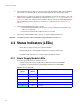
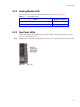
4.2.1 Power Supply Module LEDs
The Power Supply LED states are detailed in Table 4–1.
• Under Normal conditions the Power On LED should be illuminated constant GREEN
• If a problem is detected the Module Fault LED will be illuminated constant AMBER.
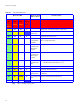
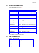
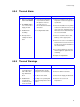
Table 4–1 Power Supply LEDs
Power On & OK
(Green)
Module Fault
(Amber)
Status
Off Off No AC power (either PSU)
Off On No AC power (this PSU only)
Off On PSU Fault (over temp, over voltage, over current, PSU fan fail)
On Off AC present, PSU on and OK
On On Fan Fault