
User guide

Getting Started
19
Chapter 2
Getting Started
2.1 Introduction
In this chapter, you are shown how to install your FC60SS enclosure into an industry standard 19 inch
rack cabinet and configure the enclosure sub-system.
Caution When connecting up FC60SS enclosures, use only the power cords supplied or cords which match the
specification quoted in section 1.5.6.
2.2 Planning Your Installation
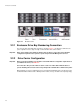
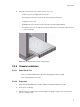
Before you begin installation you should become familiar with the configuration requirements of your FC60SS
enclosure, detailed in
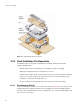
Table 2–1. The correct positions of each of the optional plug-in modules are
shown in Figure 2–1. Please refer to sections 2.7 to 2.9 (page 27 to page 32) for details of FC60SS RAID
module configurations.
Table 2–1 Enclosure System Configuration
Module Location
Drive Bays ALL drive bays must be fitted with a drive carrier module or dummy drive
carrier module; no bays should be left completely empty.
Power Supply Modules Two Power Supply modules must be fitted. Full power redundancy is
provided while a faulty module is replaced. Install the Power Supply modules
in LH rear Bays (
Figure 2–1)
Cooling Module Install in rear bay, as shown in Figure 2–1
FC60SS RAID Module Two FC60SS RAID Modules (or 1 FC60SS RAID Module plus1 blank
module) can be fitted, according to required configuration. The modules are
Installed horizontally (one above the other) in the RH rear Bay (Figure 2–1).
Caution Blank Modules or Dummy Carrier modules MUST be fitted to ALL unused bays, there will be inadequate
drive cooling if any are left open.