
User guide
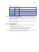
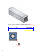
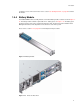
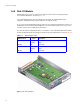
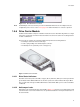
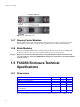
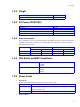

Figure 1–15 Disk I/O Module Front Panel
Introduction
13
Note The EXP’N port connects to the Host port on the next FC60SS-XPN enclosure in a multiple enclosure
configuration, please refer to section 2.9 on page 32 for further information on enclosure expansion.
1.4.6 Drive Carrier Module
The Drive Carrier Module comprises a hard disk mounted in a carrier. Each drive bay will house a single
Low Profile 1.0 inch high, 3.5 inch form factor disk drive in its carrier.The carrier has mounting locations
for SAS or SATA drives.
The front cap also supports an ergonomic handle which provides the following functions:
• Camming of carrier into and out of drive bays.
• Positive 'spring loading' of the drive/backplane connector.
• An anti-tamper lock operated by a torx socket type key.
Figure 1–16 Drive Carrier Module
1.4.6.1 Drive Status Indicators
Each drive carrier incorporates two LEDs, an upper (Green) and lower (Amber). In normal operation the
green indicator will be ON and will flicker as the drive operates The amber indicator will only be ON if
there is a drive fault. If the green LED is OFF when the amber LED is ON, a power control circuit failure
is indicated.
1.4.6.2 Anti-tamper Locks
Anti-tamper locks are fitted in the drive carrier handles (Figure 1–17) and are accessed through the small
cutout in the latch section of the handle.These are provided to disable the normal ‘pinch' latch action of
the carrier handle.