
User guide


Introduction
3
•Two Disk I/O Modules (see Figure 1–14)
Note: If only one Disk I/O module is installed then a Blank module must be fitted in the unused
slot. The module should be fitted in Slot 0 and the blank in Slot 1 (
Figure 1–5).
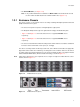
1.3.1 Enclosure Chassis
The chassis consists of a sheet metal enclosure assembly containing a Backplane printed circuit board
(PCB) and module runner system.
• The chassis front panel incorporates an integral Operator’s (Ops) Panel.
• The Backplane PCB provides logic level signal and low voltage power distribution paths.
• Figure 1–2 and Figure 1–3 show front and rear views of a populated FC60SS chassis
respectively.
• Figure 1–4 and Figure 1–5 show front and rear views of a populated FC60SS chassis
respectively.
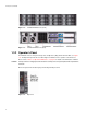
• The chassis is fitted with 19 inch Rack mounting features which enable it to be fitted to standard 19
inch racks and uses 2 EIA units of rack space (i.e. 3.5” high).
The chassis assembly contains 12 drive bays at the front, each of which accommodates the appropriate
plug-in drive carrier module. The 12 drive bays are arranged in 3 rows of 4 drives. At the rear, the chassis
assembly contains five plug-in module bays to house two Power Supply modules, a Cooling Fan module
and two FC60SS RAID modules (which are fitted horizontally), as shown in Figure 1–3
Note A drive bay is defined as the space required to house a single 1.0" high 3.5 inch disk drive in its carrier
module, shown in
Figure 1–2.
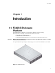
Figure 1–2 FC60SS Enclosure (Front)
.
Figure 1–3 FC60SS Enclosure (Rear)