
User guide


Enclosure User Guide
2
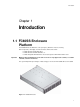
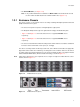
1.2 FC60SS-XPN Expansion
Enclosure
FC60SS RAID enclosure expansion is achieved by connecting FC60SS-XPN expansion
enclosures. Multiple enclosures are connected together using SAS patch cables, up to a total of five
enclosures. Please refer to section 2.9, ”Enclosures Expansion”, on page 32.
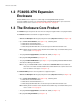
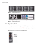
1.3 The Enclosure Core Product
The FC60SS design concept is based on an enclosure subsystem together with a set of plug-in modules.
The FC60SS SAS Enclosure Platform as supplied comprises:
• Chassis and Backplane with integral (front panel mounted) Operator’s Panel (See Figure 1–6).
• Up to 12 Drive Carrier Modules (See Figure 1–16), containing either:
– 3.0Gb/s direct dock SAS disk drives,
– 3.0Gb/s direct dock SATA disk drives, or
– 3.0Gb/s dual path SATA disk drives via an active/passive SATA mux transition card.
Note: Dummy Carriers modules must be fitted in all unused drive bays to maintain airflow, please
refer to section
1.4.7 on page 14.
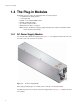
• Two plug-in Power Supply Modules,100-240V AC, 350W (see Figure 1–7)
• One plug-in Cooling Fan Module (see Figure 1–8)
• Two plug-in FC60SS RAID Modules. (See Figure 1–10), incorporating a FC60SS RAID Controller
and a Storview Management Module.
Note: If only one FC60SS RAID module is installed then a Blank module must be fitted in the
unused slot. The module should be fitted in Slot 0 and the blank in Slot 1 (where Slot 0 is the
lower slot and Slot 1 the upper, see
Figure 1–3).
The FC60SS-XPN Expansion enclosure platform as supplied comprises
• Chassis and Backplane with integral (front panel mounted) Operator’s Panel (See Figure 1–6).
• Up to 12 Drive Carrier Modules (See Figure 1–16), containing either:
– 3.0Gb/s direct dock SAS disk drives,
– 3.0Gb/s direct dock SATA disk drives, or
– 3.0Gb/s dual path SATA disk drives via an active/passive SATA mux transition card.
Note: Dummy Carriers modules must be fitted in all unused drive bays to maintain airflow, please
refer to section
1.4.7 on page 14.
• Two plug-in Power Supply Modules,100-240V AC, 350W (see Figure 1–7)
• One plug-in Cooling Fan Module (see Figure 1–8)