
Technical data


Safety Instructions and Warranty Terms 4
Manual econ sens+ Version 1.40
S0-pulse outputs
Imp - : Pulse output (Open Collector, NPN) for generated energy
Imp + : Pulse output (Open Collector, NPN) for consumed energy
GND : Common ground for Imp – und Imp +
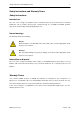
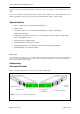
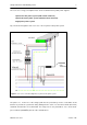
Overview RS485 model
Figure 2 shows the layout of the econ sens+ connections (RS485)
RS485 model (Modbus RTU):
A : data line B Modbus RTU
B : data line A Modbus RTU
GND : Common ground for data line A and B.
Voltage path connections
L1, L2, L3: Terminals for phases L1, L2 and L3
PE: Terminals for the PE conductor
Ext: “Extension” terminal. Is bridged with terminal L2
Current path connections
I1, I2, I3: Connection socket (RJ11) of the econ sens+ coils for current measurement
To avoid damage to the econ sens+, the maximum torque for tightening the
terminals is < 2.5 Nm.
Figure 2: econ sens + connections (RS485)
RS-485
Modbus RTU-
interface