
Technical data

Safety Instructions and Warranty Terms 9
Manual econ sens+ Version 1.40
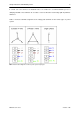
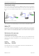
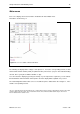
Installing the econ sens + in a 690V grid
The econ sens + can also be used in a 690 V grid (IT-System). It should be noted that a neutral
conductor is required. This is because the power supply of this device is itself designed for voltages on
the primary side to 440Vrms. When connected to a 690 V power connection so the image has to be
used according to Fig. 8.
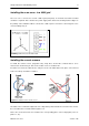
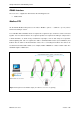
Installing the current sensors
To install the current sensors (Rogowski coils), wrap these around the conductor that is to be
measured, as shown in Fig. 9. This can be a cable or also a conductor rail.
Insert the free end of the cable into the end piece of the coil until it latches into place. The coil must
form a closed loop around the conductor.
The label on the coil must be aligned in such a way that it points towards the consumer. This ensures
the correct direction of current flow through the coil.
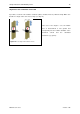
Please also ensure that each sensor matches the corresponding phase of the voltage path (coil L1 to
phase L1, etc.)
Figure 9: Installation of the current sensors
Abbildung 8: Anschlussschema 690 V-Netz