Manual econ sens + econ sens+ pro 3-phase Power Meter with Logging Function Version 1.
Content Safety Instructions and Warranty Terms .................................................................. 1 Safety Instructions ............................................................................................................... 1 Intended use ........................................................................................................................................1 Hazard warnings ..............................................................................................
Content Settings menu ................................................................................................................... 21 General information on saving settings .............................................................................................22 Time/Date submenu ..........................................................................................................................22 Network submenu .............................................................................
Safety Instructions and Warranty Terms 1 Safety Instructions and Warranty Terms Safety Instructions Intended use The econ sens+ energy consumption meter is intended solely for the measurement of electrical parameters such as voltage, current, power, electrical energy, etc.. Installation and initial operation may only be performed by electrically qualified persons.
Safety Instructions and Warranty Terms 2 All information contained in this manual was prepared to the best of our knowledge and checked with care. Nevertheless, errors cannot be completely ruled out. For this reason, the information contained in this manual is not associated with any obligation or guarantee of any kind.
Safety Instructions and Warranty Terms 3 minutes) for the last 13 months and per day for the last 10 years. No logging is performed if the time is not valid. Logs are stored after every interval. Average, minimum and maximum values are determined over the interval. The interval is expressed in seconds and can be either 600s (10min) or 900s (15min).
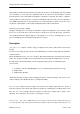
Safety Instructions and Warranty Terms 4 S0-pulse outputs Imp - : Pulse output (Open Collector, NPN) for generated energy Imp + : Pulse output (Open Collector, NPN) for consumed energy GND : Common ground for Imp – und Imp + Overview RS485 model Figure 2 shows the layout of the econ sens+ connections (RS485) RS-485 Modbus RTU- interface Figure 2: econ sens + connections (RS485) RS485 model (Modbus RTU): A: data line B Modbus RTU B: data line A Modbus RTU GND : Common ground for data line A
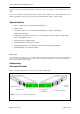
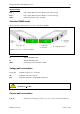
Safety Instructions and Warranty Terms 5 Ethernet connection Ethernet: Ethernet connection (RJ45) / 100 Mbit (fixed speed) Indicators and operating controls S0 model Figure 3 shows the layout of the indicators and operating controls of the econ sens+.
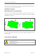
Safety Instructions and Warranty Terms 6 Further details on the connections can be found in the “Technical Data” chapter; examples of connections can be found in the “Installation Instructions”. Installation Instructions Mounting the device on the top hat rail The econ sens + energy consumption meter was designed for mounting on a top hat rail. The device is attached at an angle to the top hat rail with the upper retaining lug and locked into place with light downward pressure (see Fig. 5).
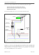
Safety Instructions and Warranty Terms 7 The econ sens+ energy consumption meter can be used with various public power supplies: 3-phase four-wire power system (with neutral conductor) 3-phase three-wire power system (without neutral conductor) Single-phase power system Fig. 7 shows the integration of the econ sens + into a 3-phase 4-wire power system.
Safety Instructions and Warranty Terms 8 If several econ sens+ devices are installed next to one another it is recommended that you use a clamping unit with series terminals. As a result it is easier to direct the fused voltage path in parallel to all devices. Table 1 shows the terminal assignment of the voltage path terminals for the various types of power system. Table 1: Connection diagrams of various power system topologies Manual econ sens+ Version 1.
Safety Instructions and Warranty Terms 9 Installing the econ sens + in a 690V grid The econ sens + can also be used in a 690 V grid (IT-System). It should be noted that a neutral conductor is required. This is because the power supply of this device is itself designed for voltages on the primary side to 440Vrms. When connected to a 690 V power connection so the image has to be used according to Fig. 8.
Safety Instructions and Warranty Terms 10 Alignment of the coil with the current flow If possible, secure the coil round the conductor (cable, conductor rail, etc.) with a tie wrap. Make sure that the loss angle of the coil is not too large (see Fig. 10). In the case of loss angles > +/-5°, the relative error of measurement is also greater and consequently also the relative deviation of the measured current and the calculated parameters (e.g. power).
Safety Instructions and Warranty Terms 11 Connecting the data outputs S0-Interface The consumption data measured by the econ sens+ is outputted via the pulse outputs Imp+ and Imp(open-collector NPN outputs) as a pulse sequence. Each output pulse is 50 ms long and corresponds to a defined amount of energy in Wh. This can be configured via the web interface. (For details see “Web Interface” chapter). The default value for this pulse weighting is 10 Wh/pulse, which corresponds to an output of 100 pulses/kWh.
Safety Instructions and Warranty Terms 12 RS485-Interface The econ sens + supported on this interface the following protocols: Modbus RTU Modbus RTU Via the RS485 Modbus RTU protocol, the values "Modbus / pulses / s submenu " p.17 ff) can be retrieved according to section. To use Modbus RTU a Modbus master is required. In a segment of up to 32 devices can be connected together. For more than 32 devices in a segment repeaters are required.
Safety Instructions and Warranty Terms 13 Connecting the network The econ sens+ energy consumption meter has a 100BASE-T network connection for web interface access. This can be connected to a PC either directly or via a node such as a hub or switch. Connect the econ sens+ to your hub/switch using a patch cable (1:1) or directly to your PC (using a crossover cable). Figure 14: econ sens+ network connection Further information on the IP address settings, etc.
Safety Instructions and Warranty Terms 14 1. Under “Start / Control Panel / Network and Internet Connections / Network Connections” doubleclick the LAN connection of the network interface card connected to the network. 2. Click the “Properties” button. 3. Select “Internet protocol (TCP/IP)” from the list and click on “Properties”. 4. Activate the options “Use the following IP address” and “Use the following DNS server addresses”. 5. Enter the parameters shown in Fig. 10 and confirm with “OK”.
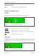
Safety Instructions and Warranty Terms 15 Home menu 1 2 3 4 Figure 12: "Home" menu screen On the home screen of the econ sens + you find the following information: 1. Menu bar to navigate the individual menus of the econ sens+ 2. Device name and current time/date 3. Language selection menu 4. Information bar Time/date settings Start-up time Operating system version Application software version Manual econ sens+ Version 1.
Safety Instructions and Warranty Terms 16 Meter menu Econ sens+ displays the measured values in tabular form in the Meter menu. This table is shown in Fig. 17. * Figure 13: econ sens+ table of measured values The following are displayed: the voltages of the phases L1, L2, L3, the corresponding currents, as well as the active and the reactive power per phase and the “power factor” (for pure sinusoidal alternating currents, this is synonymous with the familiar cos phi).
Safety Instructions and Warranty Terms 17 You can also have the voltage and the current on the three phases displayed as a curve by selecting the Curve option at the bottom left of the screen. (see Fig.18) Figure 18: Current and voltage curves Econ sens+ is able to measure and display both the generated and the consumed active power. This is illustrated in Fig.12. The consumed active power is shown in the table in blue, while the generated active power with a negative sign is shown in red.
Safety Instructions and Warranty Terms 18 Installation check routine „Installation check“ The econ sens + has a small installation check routine, called "installation check". General, it is measurement assumed coils that were all installed correctly, and the measured load has a power factor of >0.71 (phase shift between U and I <45 °). Then the table of measurements in Figure 20 is shown. In this example, a load of about 6 kW measured at L1, L2 and L3 are unloaded.
Safety Instructions and Warranty Terms 19 Note: Due to the simplicity of the installation check routine, there are also cases where there are no installation errors, the routine but still displays an error message such as: a) The measured power is exclusively produced and there is a little or no consumed power b) The power factor of the connected load is actually <0,71 Therefore, always be careful to correct installation of the measuring coils and their assignment to the voltage path to avoid misunders
Safety Instructions and Warranty Terms 20 Graph menu In the Graph menu, the measurement results are represented as a measuring curve. Fig. 22 shows an example of such a curve. Figure 14: Measuring curve in Graph menu The sum of the power/energy from the three phases is shown over a certain period of time. Using the – period and + period buttons next to the X-axis label you can toggle through the measuring curves step by step (e.g. every day of a month).
Safety Instructions and Warranty Terms 21 Events menu The Events menu is used to configure the recording of network events. These are needed for network analysis in accordance with EN 50160. This function is optional available (Pro-version). Settings menu The Settings menu is used for the parameterization of the econ sens+. All settings required for the operation of the device can be performed in the corresponding submenus. The main page of the menu shows status information.
Safety Instructions and Warranty Terms 22 General information on saving settings The overall configuration procedure for the econ sens+ is spread over several menus and various input windows. On every menu page there is an Accept button. This is used to save your inputs on the respective menu page, i.e. if you change the menu page and forget to press Accept, your inputs will revert to the default values.
Safety Instructions and Warranty Terms 23 When you click on Accept, the econ sens+ first of all checks the connection to the specified server. If there are several servers available, the device automatically selects the one with the shortest response time. Figure 25: Connection to time server was successful 2. Manual time settings: If there is no ntp time server available, the device time settings can be set manually. Activate select box Date and time = set time manually.
Safety Instructions and Warranty Terms 24 In the info area, the MAC address of the device is shown at the top. Under this is listed all of the information provided by the DHCP server, which may exist in the system. If there is no DHCP server in the system, these info fields remain empty. In the table below this the following settings can be made: Which IP address should be used? You have the choice between manual assignment of the IP address or assignment of the address by DHCP server.
Safety Instructions and Warranty Terms 25 Explanation of the settings: The European region generally has 230/400 V power systems. The 130/230 V setting must be used for power systems in the USA; 400/690V power systems are found in large manufacturing plants or wind power plants. In Europe the supply frequency is 50 Hz in the USA it is 60 Hz. Before you change any of these parameters, you should find out which setting needs to be selected.
Safety Instructions and Warranty Terms 26 Figure 29: Custom Settings menu “Electrical” (Pro version) With an optional activation key the econ sens + can be extended to the Pro version. The limits for event recording are carried out in this table (Figure 29). "Apply settings to EN501060" by selecting the limits are set to default values according to the above standard.
Safety Instructions and Warranty Terms 27 Flicker severity The 3 supply phases are checked. The method used to calculate the flicker is an approximation of the standard method. Default Value: limit x10 Voltage dips The 3 supply phases are checked. Voltage drops below 90% of the nominal supply voltage and less than 1 minute in duration are detected. A waveform is stored for this event. Default Value: 90% Voltage interruptions The 3 supply phases are checked.
Safety Instructions and Warranty Terms 28 Frequency drift The supply frequency is checked. Sudden frequency changes of more than 1Hz of the nominal supply voltage are detected. A waveform is stored for this event. Default Value 100% Vector jump The 3 supply phases are checked. Jumps of the voltage angle of more than 30° are detected. A waveform is stored for this event. Default Value 30% Neutral overvoltage The neutral voltage is checked. A voltage above 10% of the nominal supply voltage is detected.
Safety Instructions and Warranty Terms 29 Events (Proversion) submenu For each event up to 6 parameters are logged when the event occurs. Unused parameters are 0. Manual econ sens+ Version 1.
Safety Instructions and Warranty Terms 30 Pulses / s submenu Every pulse that is outputted via the two pulse outputs corresponds to an amount of energy in Wh. This “pulse weight” can be set in the Pulses/s menu. This is necessary, as the pulse output can supply a maximum pulse frequency of 10 Hz; this corresponds to 36000 pulses/h. Figure 30: pulse weighting S0-Interface The maximum admissible pulse weighting factor can be calculated with the following equation: X P * 1h P = max.
Safety Instructions and Warranty Terms 31 Modbus Pulses / s (S0/RS 485-Variante) submenu The settings for the Modbus communication is carried out in this section. Figure 31: Custom Modbus settings in the menu pulse / s (Example: Modbus TCP) Modbus Settings The setup has to be performed via HTML. Parameter Description Modbus Interface This selects which modbus protocol is used: - none - Modbus TCP - Modbus RTU (over RS485 line) - Modbus Gateway This single byte value selects the bus address.
Safety Instructions and Warranty Terms 32 Modbus register address ranges Range Contents Data size & type 2…110 Measurements - Present value 32 bit, Float 120…126 Measurements - Present value 32 bit, Float 200...216 Event flags 1 bit 300...340 Event settings 32 bit, Integer 400...406 System 16 bit, Integer 500...510 Event values 32 bit, Float 1002...1110 Measurements - Present value 32 bit, Float, gedreht 1120...
Safety Instructions and Warranty Terms 33 i(L3) 34 Current (Present value) L3 A p(L1) 36 Real Power (Present value) L1 kW p(L2) 38 Real Power (Present value) L2 kW p(L3) 40 Real Power (Present value) L3 kW q(L1) 42 Reactive Power (Present value) L1 kvar q(L2) 44 Reactive Power (Present value) L2 kvar q(L3) 46 Reactive Power (Present value) L3 kvar s(L1) 48 Apparent Power (Present value) L1 kVA s(L2) 50 Apparent Power (Present value) L2 kVA s(L3) 52 Apparent P
Safety Instructions and Warranty Terms Name 34 Register Description Phase Units i tot 120 Current, total (Present value) L1,L2,L3 A p tot 122 Real Power, total (Present value) L1,L2,L3 kW q tot 124 Reactive Power, total (Present value) L1,L2,L3 kvar s tot 126 Apparent Power, total (Present value) L1,L2,L3 kVA Modbus Register – Present value/ actual count part 2 Modbus Events The following is a list of all the coils that can be read through modbus. Every event has a single flag.
Safety Instructions and Warranty Terms 35 Modbus Event Setting Registers The event settings are also available. These are included in registers 300..340 or 1300..1340.
Safety Instructions and Warranty Terms 36 Modbus Event Value Registers Pst is the short term flicker value for the last flicker period. Plt is the long term flicker value, this is the cubic mean value over the last 12 periods.
Safety Instructions and Warranty Terms 37 Pass submenu In the Pass submenu you can change your password and user name. Figure 32: Main page of the Pass submenu When this menu is accessed, the user name that is currently used is displayed in the User Name field. To change the password or user name proceed as follows: Enter the new name and new password in the User Name and Password fields and repeat in the Verify password field.
Safety Instructions and Warranty Terms 38 Save submenu The Save submenu is used to save or restore settings from the non-volatile memory of the econ sens+. Settings that have been made in the menus are lost when the supply voltage is switched off, if they have not been saved by selecting Store changes in permanent memory.
Safety Instructions and Warranty Terms 39 Deletion of all event recordings: Deletes all data from the device resulting from event recordings (during network analysis). The network analysis is however disabled in this software version. Deletion of all output and event recordings: Deletes all measured output and event recordings from the device. Restart device Restarts the econ sens+ (not a reset) Restore default settings; measured data is retained Resets the econ sens+ back to its default settings (incl.
Safety Instructions and Warranty Terms 40 Initial Operation For initial operation of the econ sens+ proceed as follows: 1.) Before you switch the device on, check that all cable connections to the econ sens + are in place as described in the previous chapters. 2.) Switch on the circuit breakers in the voltage path; all three indicator LEDs should then light up. Check that the voltages are applied to the device and that the phases L1, L2 and L3 are correctly connected. 3.
Safety Instructions and Warranty Terms 41 Troubleshooting 1.) The S0 outputs of the Econ Sens + supply no pulses Possible causes: a.) The pulse weighting in the Pulses/s menu is set to 0 Wh/pulse -> Set the pulse weighting to > 0 Wh/pulse b.) The pulse weighting in the Pulses/s menu is set too high -> The pulse outputs of the econ sens+ allow for a maximum pulse rate of 10 Hz. Lower the pulse rate to a lower value. How to calculate the maximum admissible pulse rate is explained in the chapter Pulses/s.
Safety Instructions and Warranty Terms 42 e.) The coils for current measurement are wrongly aligned (label does not point in direction of load) -> econ sens + is able to measure both generated and consumed power/energy. The econ sens + has one pulse output for consumed power and one for generated energy. Imp+ = consumed power Imp- = generated power Only the Imp+ output is of significance for the measurement of pure energy consumption.
Safety Instructions and Warranty Terms 43 maintenance work, etc.), it may be that the sens+ has received a new IP address without you noticing. Manual econ sens+ Version 1.
Safety Instructions and Warranty Terms 44 Technical data econ sens+ basic unit mechanical Dimensions (W x H x D) Equipment class [mm] electrical 1 Operating voltage range Terminal cross-section Voltage inputs Max. clamping torque Total internal consumption mm² Nm [W] Frequency range Hz Temperature range °C Rel. error Voltage measurement % 1 [VAC] 94 x 23 x 121 IP 20 70..350 (betw. U1,U2,U3 and N) 0.15 - 4 mm² 2,5 max. 1.5 Watt with Ethernet operation 45…65 Hz 0..55°C, max.
Safety Instructions and Warranty Terms 45 Dimensions / mm Manual econ sens+ Version 1.
Safety Instructions and Warranty Terms 46 econ sens+ measuring coils: Coil 170 Coil 250 Coil 350 [mm] [mm] [mm] [m] 170 35 250 65 35 2 350 95 Measurement range [Arms] 0...400 0...1600 0..3200 Resolution Rel. error [Arms] % mechanical Overall length of coils Max.diameter of measured cable Max. bending radius Length of connecting cable electrical 0.