Custom Electronics Ltd AOV Multi-zone Control Unit Installation Document March 2008 Version 1a
Table of Contents 1) General overview 2) System Schematics i. Standard auto system ii. Auto system with break glass units iii. Auto system with detectors iv. Auto system combination v.
1) General Overview This control unit is for use with most Automatic Opening Vents and can be used with other equipment that requires forward/reverse voltage for closure. The unit will operate in conjunction with most current Fire Alarm Systems operating on 24v dc. The unit can provide battery backup so that a constant supply is applied along with visible and audible fault and conditional warnings at the control unit. Modular design allows for ease of parts replacement if needed.
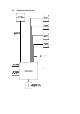
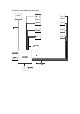
2) i Standard Auto System
2) ii Auto system with break glass units
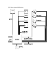
2) iii Auto system with detectors
2) iv Auto system combination
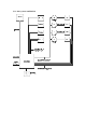
2) v Manual Control System Combination
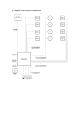
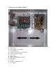
3) Internal Layout and Fixing Details A - Mains Input B – Power Supply (1 to 30 amp) C – AOV Main Board D – Indicator Connections to Front Panel E – Actuator and Link Outputs F – Zone Cards G – Battery Space H – Battery and Fault Relay Outputs I – Fixing Holes J – Keyhole K – Output to Additional Zones L – 24 v Outputs
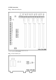
4) PCB Connections Diag 1. Motherboard Layout Diag.
5) Technical Specification Power Supply Unit 5 Amp / 10 Amp Input Supply 240v AC (+/- 10%) 50/60Hz Input Fuse 1 - 10 Zone 5Amp, 25mm UK Type quick blow. 11 Zones + 13 Amp, 25mm UK Type quick blow. Power Supply Unit Outputs Voltage Load Load: 24v DC (+/- 5%) Battery Charger: 27.6v DC Zones 1 -5. 1 Amp single output as standard Battery Charge: 1 Amp maximum Fuses Input to PCB Fuse no. FS4. 5 Amp 20mm x 5mm quick blow. Load Output Fuse no. FS2.
6) Installation Instructions 1.1 Environment The units are suitable for use in most indoor environments where an IP rating of IP30 is acceptable. 1.2 Mounting The unit should be fitted in an upright position on a solid surface using the 4 fixing holes provided. There is a “keyhole” at the upper centre of the enclosure which should only be used to assist in hanging the unit whilst the rest of the fixing holes are being marked.
7) Connection Guide 1.1 Actuator Connections Each actuator requires a 2 core cable wired direct to the control panel and each pair must be connected to its relevant zone via the terminal blocks numbered J28, J34, J40, J46, J52 on the zone distribution PCB. (This PCB is numbered CUS-268A) Refer to section 4 diagram 1 which shows the actuator connections labelled “LOAD” at the top of the PCB. 1.
8) Wiring Installation Upon installation maximum cable lengths must be adhered to, use the following table to calculate the maximum cable lengths, taking in to account the cross section of the cables. Cross Section 3 wire 5 wire 2 1.5mm 3 wire 2 1.5mm Actuator current 2 wires in parallel Amps 1 105.00m 210.00m 2 52.50m 105.00m 3 35.00m 70.00m 4 26.25m 52.50m 5 21.00m 42.00m 6 17.50m 35.00m 7 15.00m 30.00m 8 13.10m 26.20m (For ambient temperatures of 25°C) 5 wire 2 2.5mm 2 2.
AOV Multi-zone Quick Guide Connection Sheet Actuator and Triggering Connections AOV Manual Control Point Multiple Triggering Power 24V L O A D 4 - Core M 5 - Core See smoke detector wiring diagram for relay base connections. 2 - Core L I N K 7 - Core S E R I E S 2 - Core N/C 4 - Core 2 - Core Multiple trigger inputs must be in SERIES and NORMALLY CLOSED.
Quick guide • • • • • Fix unit on to wall using mounting holes provided. Remove cable ties securing zone cards. Connect mains via lower power supply and switch on. Check all power supplies are active. Check all AOV boards have power.(Timers will enable upon initial turn on). • Install batteries to relevant power supplies – removes fault indications on front panel. • Install call points, smoke testers or relays to terminals J8-J12 (fire all zones - Link).
Jumper Settings For Zone 1 to operate as a master zone the following steps must be adhered to: 5 Zone Panel Step 1 The following jumpers should be enabled for zone 1 to act as a master: J16, J18, J19 Jumpers J20 – J24 configure zones 1-5 respectively to operate alongside zone one. E.g Jumper J23 will enable zones 2-4 to act in tandem with the master zone. Therefore zone 5 will remain operating independently. Step 2 Remove Jumper J29 – Note there must be no trigger input at terminal J33 (Link1).