
Owner's Manual
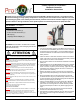
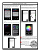
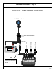
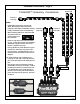
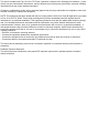
Table Of Contents

C2
[
L2
( )
C1
[
L1
( )
L
C3
[
L3
( )
C4
[
L4
( )
C6
[
L6
( )
C5
[
L5
( )
C2
[
L2
( )
C1
[
L1
( )
L
C3
[
L3
( )
C4
[
L4
( )
C6
[
L6
( )
C5
[
L5
( )
C2
[
L2
( )
C1
[
L1
( )
L
C3
[
L3
( )
C4
[
L4
( )
C6
[
L6
( )
C5
[
L5
( )
C2
[
L2
( )
C1
[
L1
( )
L
C3
[
L3
( )
C4
[
L4
( )
C6
[
L6
( )
C5
[
L5
( )
C2
[
L2
( )
C1
[
L1
( )
L
C3
[
L3
( )
C4
[
L4
( )
C6
[
L6
( )
C5
[
L5
( )
Tri splitter
ProGLOW
Input:12V Output: 5V
BB
3 2
P 1
(2) End Cap
Questions? Call us at: 1 (800) 382-1388 M-TH 8:30AM-5:30PM / FR 9:30AM-5:30PM EST
01/2021
Installation Instructions - Page 4.
ProGLOW™ Accessory Connections
C2
[
L2
( )
C1
[
L1
( )
L
C3
[
L3
( )
C4
[
L4
( )
C6
[
L6
( )
C5
[
L5
( )
Channel 3
Loop Cap
Channel 1
Loop Cap
Channel 2
Loop Cap
Notes:
1. ProGLOW™ accessories such as LED
Strips, Wire Splitters, Wire Extensions,
Loop Caps, End Caps, Headlamps, Passing
Lamps, and Wheel Lights sold separately
2. When installing LED strips, Install the LED
strip with the arrows
pointing away from
the controller.
3. Install a Loop Cap on the end of the Chan-
nel run. Loop Caps are built into Headlamp,
and Wheel Light accessories and do not
require a separate Loop Cap.
4. If using splitters to create branches in your
Channel run, install the Loop Cap on the
longest branch. Install End Caps on all of
the shorter branches. Refer to Channel 3 in
diagram.
Note: Look inside the cap to identify if it’s a
Loop Cap or End Cap. Loop Caps will have
pins inside, End Caps will be empty with no
pins.
5. Use caution when connecting the mating
ProGLOW™ accessory connectors, confirm
the mating connector is connected correct-
ly or damage will occur to the lighting ac-
cessories. The locking tab should slide on-
to the lock and lock into position. See Pho-
tos below.
LOCKED