
User's Manual
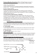
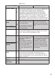

Power and Speaker Connections (Refer to Wiring Diagram on page 5.)
Note: Both Red and Yellow wires must be connected for radio to operate.
A-Main Power-Red Wire B+
Connect the RED wire (B+) to an accessory fuse that is switched OFF when the key
switch is in the OFF position and is switched ON when the key switch is switched to
the ON or accessory position.
B-Memory Back-Up-Yellow Wire B+
Connect the YELLOW wire (memory B+) to an accessory fuse that is always ON
regardless of the position of the key switch.The lead supplies power to the program
memory and the clock circuit when the radio is switched off. If there is no power on this
lead the radio will not turn on.
C-Power Antenna (Auto-Antenna) - Blue Wire
This wire can be connected to the positive switch terminal of the relay for the auto
antenna (if your car is equipped) or to th
e remote on switch of the amplifier or booster
(if equipped). NOTE: DO NOT connect this wire to a negative position or to any device
that requires high current Otherwise the radio may fail or become "fried". If your car is
not equipped with an auto antenna,leave this wire sealed and do not allow it to short to
any other positions.
Important Notice For Semi Auto Antenna
Do Not Connect the power antenna lead to this radio unless it is a fully automatic antenna. If your
antenna was controlled by a switch or knob on the original radio (ex. 1958-68 Cadillac radios) it is
not a fully automatic it is a semi automatic antenna. If you connect the antenna actuator lead of a
semi automatic antenna to this radio you will burn the circuit board in the radio. This can cause
unrep
airable damage.
D - Ground Wire - Black
Connect the black ground wire to any clean paint and contaminant free area of vehicle
chassis. NOTE: Proper grounding is essential for optimum performance of your radio.
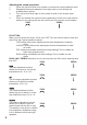
E - Speaker Wires
Connect the speaker wires as shown in Figure 2.
AUX1 and AUX2 Input
There is a right and left AUX1 input on the back
of
your radio.
Use these to listen to any portable device with standard headphone outputs
( MP3
player,
Nav unit, portable
CD etc.) The radio will control the volume level only of
this input.
Low Level Output (Line Out Jacks) Connection
The radio is equipped with low level, high impedance outputs. The low level
outputs
(RCA type Line Out Jacks) for front / rear / subwoofer will not drive speakers. If
you are connecting an amplifier or plan on it in the future, it is recommended to use
these leads. It makes for a cleaner and easier Installation.
4
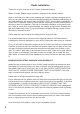
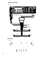
Subwoofer Out
On Pig Tail
See Figure 2
Figure 1
or AUX2 input on the front
CDC or Blukit
Input
Line-Out Rear
Right
Left
Line-Out Front
Right
Left
Auxiliary Input
Left
Right
noise peice