
Owners manual

Parts List
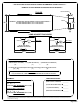
DESCRIPTIONPART NUMBERQTYITEM
1/2-13 x 1 1/4 x 2 1/2 x 3/4 SQ U-BOLTCM-1203-UBS21
HEX FLANGE NUTHFN 1213162
CARRIAGE BOLT1/2-13 x 1 1/2
83
HEX BOLT1/2 - 13 x 1 1/2
24
FW, 12, ZPFW1225
1/2 - 13 U-BOLT BUSHINGCM-C641-UB26
C-641 SUBKIT
Curt Manufacturing Inc., warrants this product to be free of defects in material or workmanship at the time of retail purchase by the original purchaser. If the product is found to be defective,
Curt Manufacturing Inc., may repair or replace the product, at their option,when the product is returned, prepaid, with proof of purchase. Alteration to, misuse of, or improper installation of
this product voids the warrant. Curt Manufacturing Inc.'s liability is limited to repair or replacement of products found to be defective, and specifically excludes liability for incidental or
consequential loss or damage.
Page 2 of 3
Installation Steps Continued
4. Repeat the cross arm installation procedure for the rear cross arm making sure to position the holes in the angle iron
towards the front of the truck. After spanning the frame, slide the cross arm towards the rear of the truck.
5. Raise the center section in position between the cross arms with the ball cylinder towards the rear of the truck.
The round hitch receiver that protrudes from the top of the center section must fit through the hole in the truck bed.
Using (8) 1/2" carriage bolts and flange nuts, attach the center section to the square holes in both cross arms.
(Finger tight only.)
6. Square the center section and cross arms across the frame. Hang the side plates from the 1/2" studs extending from the
rear cross arm. Fasten them with 1/2" flange nuts finger tight only. Next, bolt the front flange of the sideplate to the front
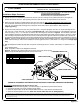
cross arm using a 1/2" x 1 1/2" hex bolt, 1/2" washer, and 1/2" flange nut as shown in Figure 2. The two holes at the front
of the sideplates should now be aligned with two holes in the frame behind the shock and shock mount. Use the 2" U-bolt
with one flange nut placed loosely to one end of the U-bolt and place the opposite end into the smaller hole at the front of
the sideplate and twist through the frame until the threaded end is protruding out the other hole of the sideplate as shown in
Figure 1. Place the U-bolt bushing over the U-bolt and into the hole of the sideplate and frame. Make sure to penetrate the
frame with the bushing in order for the sideplate to rest flat against the frame. Now attach a 1/2" flange nut and finger tight
only.
7. With the sideplates installed on both sides, torque the U-bolt flange nuts to 110 ft-lbs. and all other 1/2" fasteners to 110
ft.-lbs
in the following order:
First: Torque the U-bolts to the sideplates and frame.
Second: Torque the (8) carriage bolts from the cross arms to the center section.
Third: Torque the side plates to the front and rear cross arms.
**DO NOT EXCEED RECOMMENDED VEHICLE TOWING WEIGHT!**
WARNING!! BRAKE, FUEL, AND ELECTRICAL LINES MAY NEED TO BE LOOSENED OR REPOSITIONED
TO PROVIDE CLEARANCE FOR NEW HARDWARE.
ALL MODELS REQUIRE MODIFICATION OR REMOVAL OF HEAT SHIELDS.
ON SHORT BED MODELS, CHECK FOR ADEQUATE TURNING CLEARANCE
BETWEEN THE FRONT OF ALL TRAILERS AND THE TRUCK CAB.
(REFER TO GOOSENECK HITCH INSTRUCTIONS FOR INSTALLATION AND OPERATING PROCEDURES)
Maintenance
(Required every 30 days or prior to use)
1. Keep hitch ball lubricated regularly. Use silicone spray or equivalent to prevent wear and rust.
2. Keep hitch assembly free of dirt and other foreign debris.
3. Check for proper torque on all nuts and bolts before each use. Also check for excessive wear.
4. Check for ball wear before each use. (Note: Do not tow trailer with worn or damaged parts)
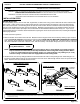
2004 - CURRENT FORD 1/2 TON TRUCKS
**NEW BODY STYLE ONLY, LONG AND SHORT BEDS**
FRONT CROSS ARM
REAR CROSS ARM
DRIVER SIDE PLATE
U-BOLT
PASSENGER SIDE PLATE
REAR OF TRUCK
U-BOLT BUSHING