
Owners manual

"THIS IS TO BE USED WITH C-615 CENTERS ONLY, 2007 TO CURRENT 1500 TRUCKS"
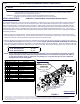
Parts List
DESCRIPTION
PART NUMBER
QTY
ITEM
2.50 DIA. x .250" ROUND HOLE SPACERCM-SP1341
1/2-13 x 4 1/8 x 4 3/4 x 1 1/2 SQ U-BOLTCM-1206-UBS22
1/2-13 x 4 1/8 x 6 x 1 1/2 SQ U-BOLTCM-1208-UBS
23
HEX FLANGE NUT
HFN 121344
HEX BOLT1/2 - 13 x 1 1/2
125
FW, 12, ZPFW12126
LOCK WASHER1/2"12
7
HEX FLANGE NUTM8-1.2528
HEX BOLTM8 - 1.25 x 2029
HEX BOLT3_4 - 10 x 5 1_2 HEX210
FLAT WASHER3_4 FW211
HEX FLANGE NUT
3_4 - 10 HFN212
.250 x 3.00 x 4.00" SPACERCM-SP58
213
11GA. BRAKE LINE BRACKETCM-BLB
114
60632
CHEVY / GMC 1500 SILVERADO / SIERRA NEW BODY ONLY - ALL BEDS
**DO NOT EXCEED RECOMMENDED VEHICLE TOWING WEIGHT!**
WARNING!!
BRAKE, FUEL, AND ELECTRICAL LINES MAY NEED TO BE LOOSENED OR REPOSITIONED TO PROVIDE CLEARANCE FOR NEW HARDWARE.
ALL MODELS REQUIRE MODIFICATION OR REMOVAL OF HEAT SHIELDS. ON SHORT BED MODELS, CHECK FOR ADEQUATE TURNING CLEARANCE
BETWEEN THE FRONT OF ALL TRAILERS AND THE TRUCK CAB.
BEFORE INSTALLING
An overhead lifting device, such as chain falls, engine hoist, or cable come-a-long, can be used to lift the center section of the
hitch in place. Lower a loop of rope or chain through the hole in the truck bed floor and attach it to the round hitch receiver
tube in the center section. Use the lifting device to raise the center section until the round hitch receiver tube that protudes
from the center section fits in the hole in the truck bed floor. Maintaining upward pressure may facilitate fastening the cross-
member to the center section, especially if the truck bed floor has been distorted downward from heavy use. If you use an
overhead-lifting device, it should be disconnected before squaring the center section across the frame, installing the sideplates
and torquing fasteners.
1) Remove spare tire and heat shield. The heat shield under the bed floor needs to be removed or a section cut out for the
hitch assembly to be installed. First, remove the heat shield from in front of the back crossmember. Next, remove the heat
shield from the back of the crossmember located near the front of the wheel well.
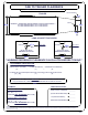
2) Mark the location for the hole in the truck bed. Measure from the tail gate end of the truck bed, by hooking a tape measure
over the back of the truck box and marking the correct location.(NOTE: DO NOT MEASURE FROM EDGE OF TAILGATE)
Next, mark the center between the wheel wells. This marks the center point for the drill hole. This hole location is critical for
the correct installation of this hitch. Measure, mark, and saw carefully. This location will put the ball 4"-6" in front of the axle.
69.30" Bed Installation 42 7/16"
78.70" Bed Installation 42 7/16"
97.60" Bed Installation 49 1/2"
NOTE: If truck has a plastic bed liner, you may drill through both, but it is more difficult to accurately locate the
midpoint between the wheel wells and to keep the bed liner from moving while cutting the hole. Make a
4" hole at this location using a 4" hole saw, or by making a 4" circle and cutting it out with a saber saw
equipped with a metal cutting blade.
FIGURE 1
REAR OF TRUCK
FRONT OF TRUCK
INSTALLATION STEPS
**REMOVE ALL REAR WINDOW ACCESSORIES BEFORE TOWING**
PAGE 1
Curt Manufacturing Inc., warrants this product to be free of defects in material and/or workmanship at the time of retail purchase by the original purchaser. If the product is found to be defective,
Curt Manufacturing Inc., may repair or replace the product, at their option, when the product is returned, prepaid, with proof of purchase. Alteration to, misuse of, or improper installation of
this product voids the warranty. Curt Manufacturing Inc.'s liability is limited to repair or replacement of products found to be defective, and specifically excludes liability for incidental or
consequential loss or damage.
7/1/13
FRONT CROSSARM
REAR CROSSARM
SHORT BOX MOUNTING HOLE
LONG BOX MOUNTING HOLE
DRIVER SIDE PLATE
BRAKE LINE
BRACKET
SHOWN WITH C-615
INSTALLED
(NOT INCLUDED IN SUBKIT)
6
7
5
4
1
14
9
2
8
12
11
13
10
WARNING!! ON TWO WHEEL DRIVE TRUCKS A CLEARANCE CHECK MUST BE PERFORMED WHEN TRUCK IS LOADED
AND UNLOADED TO VERIFY THE INVERTED BALL WILL NOT INTERFERE WITH THE TOP OF THE DIFFERENTIAL