
Owners manual

Curt Manufacturing LLC., warrants this product to be free of defects in material and/or workmanship at the time of retail purchase by the original purchaser. If the product is found to be defective,
Curt Manufacturing LLC., may repair or replace the product, at their option, when the product is returned, prepaid, with proof of purchase. Alteration to, misuse of, or improper installation of
this product voids the warranty. Curt Manufacturing LLC.'s liability is limited to repair or replacement of products found to be defective, and specifically excludes liability for incidental or
consequential loss or damage.
KEEP IN VEHICLE FOR FUTURE REFERENCE
60630 QUICK GOOSE 2 Page 2 of 6
WARNING DO NOT invert the ball when carrying heavy loads on 2 wheel drive trucks. The ball may hit the top of the differential,
brake lines, electrical lines, or sensors.(NOTE: Do not invert ball on any Toyota Tundra models)
Warning!! Brake, Fuel, or Electrical lines may need to be loosened or repostioned to provide clearance for new hardware. The
installation of this hitch may require modification to heat shields.
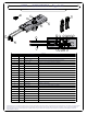
Installing the 60630 Quick Goose
1) The 60630 Quick Goose 2 has been totally assembled, cycled, and partially disassembled for packaging and shipment. The
Quick Goose Ball should be in its lower position upon arrival. The Ball is under spring pressure to force the Ball upward. For this
reason, the Choker (secured with a nylon tie strap) is holding the Ball in the location described. EXTREME CAUTION SHOULD
BE EXERCISED WHILE HANDLING AND INSTALLING THE 60630. INJURY MAY OCCUR IF THE BALL SHOULD SPRING
UPWARD. KEEP FINGERS, HANDS, AND FACE CLEAR OF THE BALL AND ITS MECHANISMS.
2) Position the 60630 Quick Goose 2 over the rear axle and up to the rear cross arm with the cylinder offset towards the rear of
vehicle. If the rear cross arm is manufactured from angle iron, insert (4) 1/2 - 13 UNC Carriage Bolts through the cross arm first
and continue through the 60630. Install (4) 1/2" Flange Nuts finger tight. DO NOT TIGHTEN AT THIS TIME. If the rear cross arm
is manufactured from solid steel and has threaded holes, install (4) 1/2 - 13 UNC Bolts equipped with Lock Washers and Flat
Washers. Insert the Bolts through the 60630 first and thread into the solid cross arm. DO NOT TIGHTEN AT THIS TIME.
3) Move the front cross arm back towards the 60630 Quick Goose 2. As in step 2, use the appropriate hardware combination to
secure the hitch.
4) Torque all 1/2’’ Hardware to 75 ft-lbs.
Installing the 60630 Pull Rods
NOTE: In some applications a notch may need to be cut in the fender wall between
the bed supports for rod operating clearances.
1) Carefully cut, remove, and dispense the nylon tie strap securing the Choker. DO NOT ALLOW THE CHOKER TO BE
REMOVED FROM ITS PRESENT LOCATION UNTIL STEP 2).
2) Using suitable tooling, hold the mechanisms and linkages stationary to prevent the Ball from immediately moving upward while
removing the Choker.
3) Remove the Choker and slowly allow the Ball to travel upward. Replace the Choker with the Ball in its upward position.
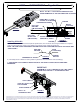
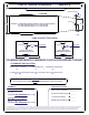
4) Apply a small amount of multi-purpose grease inside the Choker Pull Rod hole. Place the Compression Spring between the
Inner Rod Guide and the Choker. Ensure the Compression Spring is fully seated in the Choker Counterbore. SEE FIGURES 1
and 2 OF ASSEMBLED UNIT ON PAGE 2.
5) Insert the Pull Rod with the Red Vinyl Grip through the driver's side fenderwell as required. Continue into and through the Outer
Guide. To continue into the Inner Guide, rotate the Pull Rod as required to pass the first Hardened Dowel Pin through the Guide
Tube. Continue through the Compression Spring and seat fully into the Choker.
Insert the M6 x 1 x 35mm Hex Bolt as shown and secure with a M6 x 1 Nylon Lock Nut. Tighten securely.
NOTE: If required, this Pull Rod may be shortened by cutting with a hacksaw at the scribed line.
Lightly file sharp edges after cutting and install as described above.
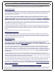
6) Install the Pull Rod with the Black Vinyl Grip through the other holes of the Outer and Inner Guides. Attach to Linkages as
shown using another M6 x 1 x 35mm Hex Bolt and M6 x 1 Nylon Lock Nut.
Lightly tighten Lock Nut and back off a minimum of 1/2 turn. Linkages must not be compressed against Pull Rod.
Threads must extend past Nylon Lock.
NOTE: This Rod may be shortened if required by simply installing the M6 x 1 x 35mm Hex Bolt in the second hole from
the end of the Pull Rod. Detach Extension Spring from its current location and reattach through the hole at the end of the
Pull Rod.
IMPORTANT:
1) Check that all 60630 hardware has been torqued as specified.
2) Check that all side plate hardware has been torqued. Some Hardware listed will not apply to your application.
(3/8" Hardware 30 ft-lbs / 1/2" Hardware 75 ft-lbs / 5/8" Hardware 150 ft-lbs / 3/4" to 1" Hardware 250 ft-lbs)
2/23/2011