CURT Manufacturing, LLC 6208 Industrial Drive Eau Claire, WI 54701 888.265.5615 Phone 715.838.7524 Fax Quick goose II gooseneck www.curtmfg.com Instruction manual Installer: Read and understand this manual. Fully instruct and demonstrate the operation of this gooseneck hitch to the end user. Include the importance of observing all warnings. Provide this manual in its entirety to the end-user.
60630 2/23/2011 QUICK GOOSE 2 Page 2 of 6 KEEP IN VEHICLE FOR FUTURE REFERENCE WARNING DO NOT invert the ball when carrying heavy loads on 2 wheel drive trucks. The ball may hit the top of the differential, brake lines, electrical lines, or sensors.(NOTE: Do not invert ball on any Toyota Tundra models) Warning!! Brake, Fuel, or Electrical lines may need to be loosened or repostioned to provide clearance for new hardware. The installation of this hitch may require modification to heat shields.
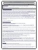
60630 QUICK GOOSE 2 Page 3 of 6 KEEP IN VEHICLE FOR FUTURE REFERENCE NOTE: ALL M6 x 1 x 35mm BOLTS ARE INSTALLED FROM THE MIDDLE OF THE UNIT AND POINT OUTWARD. INSERT M6 x 1 x 35mm HEX BOLTS AS SHOWN CHOKER COMPRESSION SPRING SHAFT COLLARS BOLT FIGURE 1 BOLT PULL ROD RED GRIP (CM-C630-PRRW) PULL ROD BLACK GRIP (CM-C630-PRL) DO NOT OVER TIGHTEN.
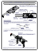
60630 QUICK GOOSE 2 Page 4 of 6 KEEP IN VEHICLE FOR FUTURE REFERENCE 60630 OPERATION 1) To raise Ball to the towing position, rotate the Red Grip Choker Pull Rod 45 degrees counterclockwise and pull to its full extension. Spring tension should raise the Ball. Typically further assistance is not required, however, in the event assistance is required, push in on the Black Grip Linkage Pull Rod while maintaining the Red Grip Choker Pull Rod at its full extension.
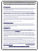
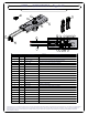
60630 QUICK GOOSE 2 Page 5 of 6 KEEP IN VEHICLE FOR FUTURE REFERENCE 21 7 22 14 1 15 12 11 5 16 2 6 3 4 8 17 13 18 19 10 20 9 Parts List ITEM QTY PART NUMBER 1 1 CM-C630-TPW TOP PLATE WELDMENT / CARBIDE BLACK DESCRIPTION 2 1 CM-C630-FLS FLIPPER LEVER SHAFT / ZINC PLATED 3 2 16 ID x 12_7-SSCA 16mm SOLID SHAFT COLLAR WITH SET SCREW / CLEAR ZINC 4 2 16_2 ID x 3-NW 16.
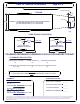
***DO NOT EXCEED VEHICLE MANUFACTURER'S RECOMMENDED TOWING CAPACITY.*** CAB TO TRAILER CLEARANCE 2/23/2011 Page 6 of 6 **REMOVAL OF REAR WINDOW ACCESSORIES MAY BE REQUIRED.** COUPLER OVERHANG TRAILER 4 in (W) COUPLER 96 in 72 in ***GENERALLY, TAPERED NOSE TRAILERS ADHERE TO THE FOLLOWING DESIGNS:*** 8 FT. WIDE TRAILERS TAPER TO 6 FT. AT THE COUPLER. 7 FT. WIDE TRAILERS TAPER TO 5 FT. AT THE COUPLER.