
Owners manual

Warning!!
Carefully examine the location of fuel lines, brake lines, and electrical wires BEFORE INSTALLATION.
Brake, fuel, and electrical lines may need to be loosened or repositioned to provide clearance for new hardware. The
installation of this hitch may require modification or removal of heat shields. The use of overload springs, air bags, etc.
may be required when towing heavy loads.
Installing C-620 Turnover Gooseneck After Cross Arm Sub-kit Installation
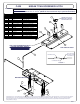
1) Position the C-620 over the rear axle and up to the rear cross arm with the cylinder facing the correct
direction for decided application. Install four 1/2" x 1 3/4" carriage bolts into the C-620 first, then through
the rear cross arm and secure with 1/2" flange nuts, finger tighten.
2) Move the front cross arm to the C-620 and install the 1/2" x 1 3/4" carriage bolts into the cross arm then
through the C-620 and secure with 1/2" flange nuts.
3) Torque all 1/2" hardware to 75 ft-lbs.
Installing Safety Chain Attachments
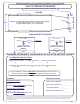
1) From under the truck use the C-620 gooseneck as a template to drill four 1/2” holes for the safety chain
attachments.
2) Using a 1/2” drill bit, drill the center of each slotted hole in the gooseneck.
(Note: Be sure the holes are
drilled in the lower rib section of the truck bed as shown in FIGURE 1).
3) From inside the truck box place the two U-bolts through the predrilled holes in the bed of the truck.
4) From beneath the truck place a spring and nylock nut on each of the four U-bolt legs. Tighten the nylock
nuts until flush with the bottom of the U-bolt.
Installing handle / lock
1) Insert Locking Pin (7) into the ball cylinder with handle rod hole located on top.
2) Slide foam grip (10) onto handle rod.
3) Insert handle rod from outside vehicle, through the hole in the C-620 endplate, and through the rod guide
as shown. (Handle rod may be installed on driver side or passenger side, depending on preference).
4) Slide the compression spring (8) over handle rod before inserting the handle rod into the locking pin.
Insert handle rod into locking pin and secure with #10 screw (5) and nylock nut (4) as shown.
(Note: Use 1-2 additional 3/8” washers (6) as needed to ensure proper pull length of locking pin)
.
Caution!!!
1. Check that all 1/2" hardware has been torqued to 75 ft-lbs (12 - 1/2" Flange Nuts total)
2. Check that all side plate hardware has been torqued. Some hardware listed will not apply to your
application.
3/8" to 30 ft-lbs.
1/2" to 75 ft-lbs.
5/8" to 150 ft-lbs.
3/4" to 250 ft-lbs.
1" to 250 ft-lbs.
3. Re-attach Brake, Fuel, and Electrical lines so they do not contact any of the added fasteners.
C-620 Operation
1. Pull the handle out as far as possible and rotate clockwise until the locking pin is disengaged and locked
out.
2. Insert ball in the tow position into the cylinder by aligning the ball groove with the cylinder pin. If the groove
and pin are not aligned simply rotate ball until the ball drops into place.
3. Rotate handle counter clockwise until locking pin snaps back into position. (Note: Be certain the locking
pin passes completely through the ball and securely into the cylinder.
C-620 Installation check
1. Set ball in towing position and handle in locked position.
2. Connect the trailer to the hitch ball.
3. Check truck box clearance, there should be a minimum clearance of 6" between the bottom of the trailer
overhang and the top of the box sides. Verify clearance between the truck and trailer at cab and box
corners.
Maintenance (Required every 30 days or prior to use)
1. Keep hitch ball lubricated regularly. Use silicone spray or equivalent to prevent wear and rust.
2. Keep hitch assembly free of dirt and other foreign debris.
3. Check for proper torque on all nuts and bolts before each use. Also check for excessive wear.
4. Check for ball wear before each use.
(Note: Do not tow trailer with worn or damaged parts)
.
Curt Manufacturing Inc., warrants this product to be free of defects in material and/or workmanship at the time of retail purchase by the original purchaser. If the product is found to be defective,
Curt Manufacturing Inc., may repair or replace the product, at their option, when the product is returned, prepaid, with proof of purchase. Alteration to, misuse of, or improper installation of
this product voids the warranty. Curt Manufacturing Inc.'s liability is limited to repair or replacement of products found to be defective, and specifically excludes liability for incidental or
consequential loss or damage.
C-620 NISSAN TITAN GOOSENECK HITCH
PAGE 2