
Owners manual
**CRITICAL**
THE FRONT CROSSARM (CM-60604-FCA) IS IDENTIFIED
BY A NOTCH AS SHOWN ABOVE
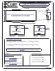
QUICK HOLE DIMENSIONS
SHORT BED INSTALLATION 44"
LONG BED INSTALLATION 48 7/8"
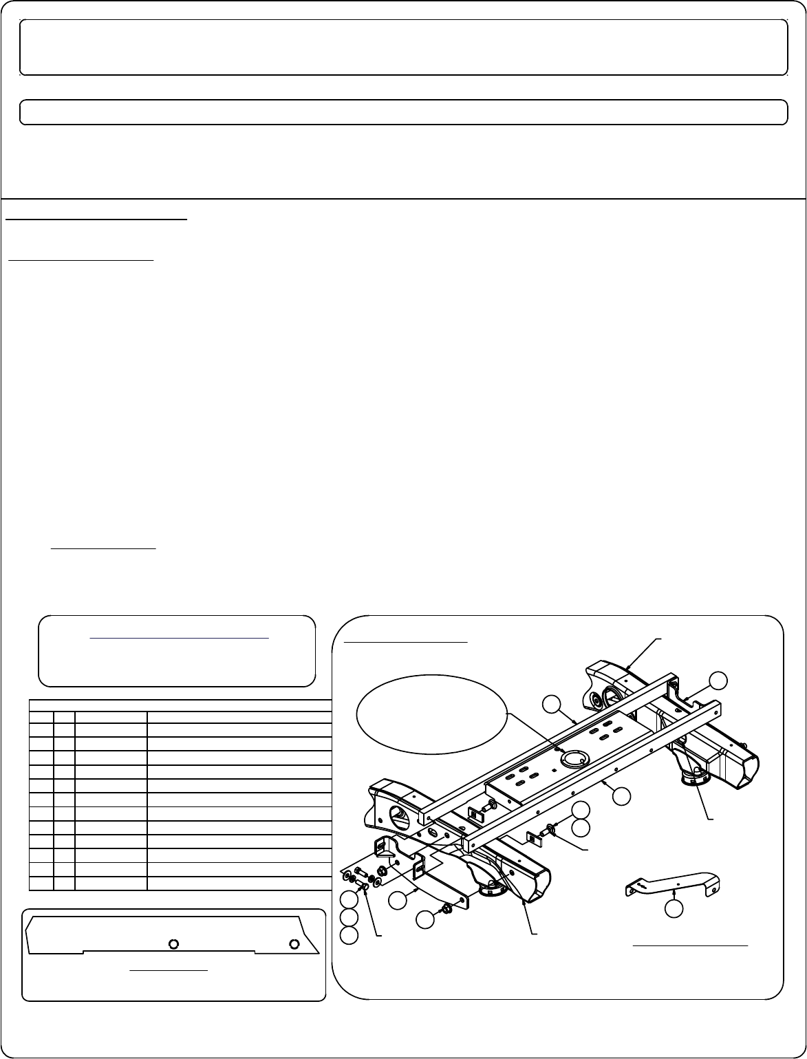
Parts List
DESCRIPTIONPART NUMBERQTYITEM
WELDMENT ASSEMBLYCM-60604-DSW11
WELDMENT ASSEMBLYCM-60604-PSW
12
1" x 2" FRONT CROSS ARMCM-60604-FCA
13
1" x 2" REAR CROSS ARMCM-60604-RCA
14
.250 x 1.25 x 2.50" SQUARE HOLE SPACERCM-SP9
45
CARRIAGE BOLT5/8-11 x 1 3/446
HEX FLANGE NUT5/8-114
7
HEX BOLT1/2 - 13 x 1 1/2128
LOCK WASHER1/2"129
FW, 12, ZPFW121210
5/8" FISHWIRE5_8 FISHWIRE
211
16GA. TEMPLATECM-60604-T
112
FIGURE 1
60604
CHEVY-GMC 2500 / 3500 SHORT AND LONG BED
**DO NOT EXCEED RECOMMENDED VEHICLE TOWING WEIGHT!**
WARNING!! BRAKE, FUEL, AND ELECTRICAL LINES MAY NEED TO BE LOOSENED OR REPOSITIONED TO PROVIDE CLEARANCE FOR NEW HARDWARE.
ALL MODELS REQUIRE MODIFICATION OR REMOVAL OF HEAT SHIELDS. ON SHORT BED MODELS, CHECK FOR ADEQUATE TURNING CLEARANCE
BETWEEN THE FRONT OF ALL TRAILERS AND THE TRUCK CAB.
BEFORE INSTALLING
An overhead lifting device, such as chain falls, engine hoist, or cable come-a-long, can be used to lift the center section of the
hitch in place. Lower a loop of rope or chain through the hole in the truck bed floor and attach it to the round hitch receiver
tube in the center section. Use the lifting device to raise the center section until the round hitch receiver tube that protudes
from the center section fits in the hole in the truck bed floor. Maintaining upward pressure may facilitate fastening the cross-
member to the center section, especially if the truck bed floor has been distorted downward from heavy use.
1. Remove spare tire and heat shield. The heat shield under the bed floor needs to be removed or a section cut out for the
hitch assembly to be installed. First, remove the heat shield from in front of the rear crossmember. Next, remove the heat
shield from the back of the crossmember located near the front of the wheel well. Remove plastic wheel well covers if vehicle
is equipped with them.
**NOTE: Before installing crossarms, run a 1/2-13 bolt or 1/2"-13 tap through crossarm holes to remove any
powder coating or debris.**
2. Install the rear crossarm by sliding it between the frame and the floor of the truck bed above the passenger side rear tire.
After spanning the frame rails, rotate the cross arm vertically with the holes towards the bottom.
3. Install the front crossarm by sliding it between the truck frame and the floor of the truck bed above the passenger side rear
tire (SEE FIQURE 1)
. With the crossarm spanning the truck frame rails, rotate it vertically with the holes towards the bottom.
4. Install the sideplates (flanges toward the front of the vehicle), aligning the holes in the side plates with the existing holes
in the frame as shown.
FIGURE 2
REAR OF TRUCK
FRONT OF TRUCK
INSTALLATION STEPS
**REMOVE ALL REAR WINDOW ACCESSORIES BEFORE TOWING**
PAGE 1 OF 3
Curt Manufacturing Inc., warrants this product to be free of defects in material and/or workmanship at the time of retail purchase by the original purchaser. If the product is found to be defective,
Curt Manufacturing Inc., may repair or replace the product, at their option, when the product is returned, prepaid, with proof of purchase. Alteration to, misuse of, or improper installation of
this product voids the warranty. Curt Manufacturing Inc.'s liability is limited to repair or replacement of products found to be defective, and specifically excludes liability for incidental or
consequential loss or damage.
7/13/2012
WARNING!! ON TWO WHEEL DRIVE TRUCKS A CLEARANCE CHECK MUST BE PERFORMED WHEN TRUCK IS LOADED
AND UNLOADED TO VERIFY THE INVERTED BALL WILL NOT INTERFERE WITH THE TOP OF THE DIFFERENTIAL
**FISHWIRES NOT SHOWN**
SHOWN WITH
60607 INSTALLED
(NOT INCLUDED IN SUB KIT)
ACCESS HOLE
(BOTH SIDES)
TORQUE ALL 5/8"
HARDWARE TO 210 LB-FT
TORQUE ALL 1/2"
HARDWARE TO 110 LB-FT
8
9
10
1
7
6
5
4
3
2
12
DRIVER SIDE
FRAME RAIL
PASSENGER SIDE
FRAME RAIL