
Installation Guide


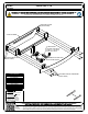
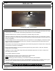
Table Of Contents

HAVING INSTALLATION QUESTIONS? CALL TECHNICAL SUPPORT AT 877-287-8634
INSTALLATION STEPS
PERIODICALLY CHECK THIS RECEIVER HITCH TO ENSURE THAT ALL FASTENERS
ARE TIGHT AND THAT ALL STRUCTURAL COMPONENTS ARE SOUND.
CURT Manufacturing LLC., warrants this product to be free of defects in material and/or workmanship at the time of retail purchase by the original purchaser. If the product is found to be defective,
CURT Manufacturing LLC., may repair or replace the product, at their option, when the product is returned, prepaid, with proof of purchase. Alteration to, misuse of, or improper installation of this
product voids the warranty. CURT Manufacturing LLC.'s liability is limited to repair or replacement of products found to be defective, and specifically excludes liability for incidental or consequential
loss or damage.
CADILLAC CT6
9/29/2020
12160
PAGE 2 of 2
1. Remove underbody panel by removing (3) nuts using a 10mm socket and remove (12) screws along outer edge
of fascia using T-15 Torxbit Socket. Set underbody panel aside for trim and reinstallation.
2. Pull back wheel well cover to remove (4) screws (2) on each side using 7mm socket.
3. Inside the trunk along the plastic liner guard use plastic pry bar to remove (2) caps, (1) on each side, to access
and remove (2) bolts, (1) on each side, using T-45 Torxbit Socket. Gently remove plastic trunk liner guard and set
aside for reinstallation.
4. To access taillight removal, remove (4) plastic clips, (2) on each side. To remove taillights, pull back trunk carpet
locate and remove (8) nuts using 8mm socket, (4) on each side. Unclip electrical harness and gently remove
taillight, set aside for reinstallation.
5. Gently remove rear bumper fascia by releasing the press-in tabs along top portion of bumper fascia. Unclip motion
sensor harness. Set aside for reinstallation.
6. Remove the bumper beam by removing (2) nuts and (2) bolts using 13mm socket, on each side. Set aside
bumper beam for reinstallation.
7. Install hitch on rear of vehicle frame using existing studs. Reinstall bumper beam over hitch. Loosely secure
with existing vehicle hardware.
8. Torque all M10 hardware to 45 ft-lbs.
9. Trim underbody panel as shown in the trim diagram using aviation shears.
NOTE: All dimensions are approximate, confirm fit prior to trim.
NOTE: Removing (2) corner crush tabs (1) on each side of fascia may ease installation.
10. Reinstall rear bumper fascia removed in step 5. Reinstall taillights removed in step 4. Reinstall trunk liner guard
removed in step 3. Reinstall underbody panel removed in step 1. Reinstall all fasteners removed.
Installation complete.
UNDERBODY PANEL TRIM DIAGRAM
3.00"
2.00"
CENTER LINE
OF VEHICLE