
Owners manual

Green
indicator
showing
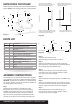
Handle in
vertical position
Red indicator
not showing
Figure 5
A
Detail A Detail B
B
Front
of truck
Figure 4
Base rail hitch pin illustration
Base rail
5th Wheel heAd
INStAllAtIoN
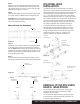
To install the 16515 5th wheel head (Figure 6), slide the
16515 cross member weldment into the R16 roller as shown.
Select desired height using the adjustment holes in the cross
member weldment. From the inside, insert four supplied
1/2" x 1 3/4" bolts into the four holes of the cross member
weldment into the R16 roller. Place 1/2" nylock nuts on each
bolt. Torque to 75 ft/lbs. Place the 16515 5th wheel head into
the cross member weldment saddle, insert supplied 3/8"
hitch head pins and secure with hitch pin clips. The R16 is
now ready for operation. See 'Operation Instructions'.
To install the 16520 5th wheel head (Figure 7), select
desired height using the adjustment holes in the cross
member weldment. Place the four supplied 14mm bolts
through the holes and secure them with the nylock nuts.
Torque all four bolts to 100 ft-lbs. The Q16 is now
ready for operation. See 'Operation Instructions'.
RemoVAl of the 5th Wheel
heAd & 16560 RolleR
For removal of the 5th wheel head from the R16 roller,
reverse the steps found under the '5th Wheel Head
Installation' for your model.
For removal of the 16560 R16 roller, remove pins & clips
from Step 9 found under the 'Assembly Instructions' on
the previous page. See Figure 4.
16520 Q16
5th wheel head
16515 E16
5th wheel head
Hitch head
pin & clip
Torque 14mm bolts
to 100 foot lbs.
Torque 14mm
bolts to 75 foot lbs.
16515
cross member
weldment
14mm bolts
Nylock nuts
Figure 6
Figure 7
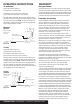
Step 8
Slide cross member weldment (#5) between the DS roller
assembly (#11), PS roller assembly (#10) and over the lock
rod assembly as shown in Figure 1. Secure with 10mm flat
head bolts and torque to 35 foot lbs.
Step 9
Place the assembled R16 roller into the base rails (#15) and
pin in place with the supplied hitch pins & clips (#13, #14).
CAUTION: Be sure that all base rail hitch pins are
positioned as shown in Figure 4 below and that all
clips are secured before towing.
Step 10
Pull handle out and rotate as shown on the operation decal
on the roller. Roller should move smoothly fore and aft on
the rails. NOTE: When the R16 roller is locked in its fore and
aft positions the lock bar handle should be vertical. The red
indicator will not be showing and the green indicator will be
showing. See Figure 5 below.
Step 11
If the unit binds, make sure all bolts are torqued to proper
specifications. Make sure base rails are square and parallel.
PAGE 3 • 16560-INS-RB • 1.800.798.0813 • NEED ASSISTANCE? • CURTMFG.COM