
Owners manual
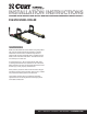

The R16 roller is to be used with 5th wheel trailers weighing
up to 16,000 lbs. Never use on trailers exceeding 16,000 lbs.
CAUTION: The R16 roller will reposition your 5th wheel hitch
12" rearward. However, this will not guarantee complete truck
cab/trailer clearance when towing.
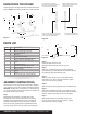
Step 1
Before beginning assembly of the R16 roller, check
the base rails in your truck to be sure they are properly
installed and are parallel with each other. The diagonal
dimensions should be the same, see Figure 2. With the
base rails correctly positioned, the assembled R16 roller
will drop into the slots on the top surface of the base rails.
ASSembly INStRuctIoNS
Ensure rail kits are installed
according to rail kit manufacturer's
recommended specifications
Front of truck
Rear edge of truck bed
Rear edge of truck bed to
rear edge of mounting rail
Measure diagonal from same
reference point. Measurement
should be the same
Each mounting rail must have a bolt
in either of the marked holes. Check
for obstructions before drilling
Figure 2
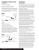
Figure 3
6mm fastener6mm fastener
Grease
Grease
7
11
8 1 6
9
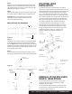
PARtS lISt
uNPAcKING the RolleR
Item# Qty Description
1 1 Outer tube
2 4 Flat head socket head cap screw
3 3 Hex head cap screw
4 3 Nylock nut
5 1 Cross member weldment
6 1 Lock rod weldment, passenger side (PS)
7 1 Lock rod weldment, driver side (DS)
8 1 Handle
9 1 Compression spring
10 1 Roller assembly, passenger side (PS)
11 1 Roller assembly, driver side (DS)
12 4 Spacer, neoprene
13 4 Rail pin
14 4 Rail clip
15 1 Set of mounting rails, ordered separately
Inspect all parts for damage and verify that all items listed are
present. NOTE: The mounting rail kit (#15) is sold separately.
Figure 1
9
6
1
3
7
15
4
12
11
13
14
2
10
5
8
Step 2
Grease the ends of the lock rod
weldments (#6) and (#7) as shown in Figure 3.
Step 3
Slide lock rod weldment (#7) into the driver side (DS)
roller assembly (#11) and slide lock rod weldment (#6) into
the passenger (PS) roller assembly (#10).
Step 4
Slide the outer tube (#1) over lock rod weldment (#6)
until holes line up. Secure with 6mm fastener. Tighten
until nylock nuts are fully engaged.
Step 5
Slide compression spring (#9) over lock rod weldment (#7).
Step 6
Slide lock rod weldment (#7) with compression spring (6)
into outer tube (#1) until the holes line up. Secure with 6mm
fastener. Tighten until nylock nuts are fully engaged.
Step 7
Slide handle (#8) over lock rod weldment (#7) until
the holes line up. Secure with 6mm fastener. Tighten
until nylock nuts are fully engaged.
CURTMFG.COM • NEED ASSISTANCE? • 1.800.798.0813 • 16560-INS-RB • PAGE 2