
Owners manual

GENERA L INSTRUCTIO NS FOR M OUNT IN G R AIL IN ST ALLAT IO N
TO O LS
3/16” drill 3/4” Socket & Open End W rench
17/32” drill 100 lb-ft Torque W rench
1” drill (Some D odge application only) “C” Clam ps
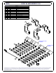
1. T he following instructions should be used to mount the 5
th
wheel. Care and attention to detail will ensure a
quality installation. Check parts against parts list to become familiar with parts in kit. (See Fig. 1)
2. Raise rear of truck high enough to allow jack stands to be placed under rear spring hanger bracket of truck. T his
will provide maximum room to install the 5
th
wheel brackets.
W AR NIN G:
If the truck is raised, be sure that the truck is properly blocked and restrained to prevent
the truck from falling. Failure to do so may result in the truck suddenly falling, causing
death or serious injury.
3. Do not install mounting rails over plastic bed liners. Plastic bed liners must be cut out of the way. M ounting
rails may be installed on spray in liner.
Note
: Consult installer for recomm ended curing time.
4. Use only the supplied bolts, nuts, and washers to install this kit. All installation hardware is grade 5 unless
otherwise specified.
5. Specific instructions for most commonly used vehicles are included. If these instructions do not apply to your
vehicle, be sure that each end of each base rail is connected to the vehicle fram e. Each fram e bracket m ust be bolted
to the vehicle frame with two bolts, unless optional weld is used.
CAUT ION:
These instructions are guidelines only. Actual installation is the responsibility of the
installer and the ow ner. A lw ays measure truck and trailer before installing hitch to be
sure that there is clearance at the cab and at the bumper to allow for turns.
To prevent the trailer from hitting the cab with the trailer turned 90° , the center of the hitch should be at least 52”
from the back of the cab when using a long bed truck. (Actual distance required will depend on trailer width and
king pin location.) Short bed (M inimum 38” from back cab to axle center line) trucks require a minimu m of a 13”
extended pin box for regular maneuvers and do not apply.
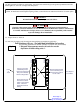
6. M easurements are given from Rear Edge of truck bed to rear edge of the mounting rail closest to the Rear Edge
of truck for most vehicle applications (See Fig. 2).
7. Center hitch betw een fender w ells and make sure rails are square. Adjust position of rails until both
diagonal measurements are the same. This should allow installation of a gooseneck or other 5
th
w heels to
these rails (See Fig. 2).
CAUTIO N:
Check for obstructions before drilling. Failure to do so could result in damaged fuel or
brake lines, structural m em bers, etc. CUR T M AN UFACTU RIN G does its best to
comm unicate tow vehicle manufacturer changes; however, it is ultimately the
responsibility of the installer to prevent damage due to installation.
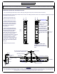
8. Drill 10 holes identified in Fig. 2. (Hole location will vary for individual vehicle applications.) Drill all holes
with 3/16” drill and enlarge them with a 17/32” drill. Always use sharp drill bits. A 3/16” pilot hole will greatly
speed drilling larger holes. Install 1/2-13 x 2” carriage bolts into holes. Install 5/16” thick slotted spacer above or
below bed to fill corrugations in bed floor.
NO TE: For Toyota Tundra application, part #16302 spacer kit is
required. Stack (1) 3/16” and (1) 5/16” thick slotted spacer to avoid crushing of truck bed.
9. Install mounting brackets onto carriage bolts. Secure bolts through mounting brackets with lock washers and
hex nuts. Secure the other four bolts through the bed with flat washers, lock washers, and nuts.
For Installation Assistance or Technical Help, Call 1-800-798-0813