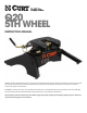
Q20 5th Wheel CURT Manufacturing, Inc. 6208 Industrial Drive Eau Claire, WI 54701 888.265.5615 Phone 715.838.7524 Fax www.curtmfg.com Instruction manual Installer: read and understand this manual. Fully instruct and demonstrate the operation of this 5th wheel hitch to the end user. Include the importance of observing all warnings contained herein, including warning labels on 5th wheel hitch mid section. Provide this manual in its entirety to the end-user.
Table of Contents Warning Statements Assembly and Installation Unpacking Coupling and Locking Coupling Pull test Uncoupling and Resetting Removal and Reinstallation Maintenance Requirements Warranty Page 2 Page 3 - 4 Page 3 Page 5 - 7 Page 7 Page 7 Page 8 Page 9 - 10 Page 11 - 12 Page 12 Warning statements • Never exceed the rated towing capacity of your vehicle. Trailer and contents combined must not exceed tow vehicle, hitch, and or trailer tow ratings.
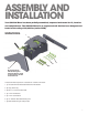
Assembly and Installation Your Q20 5th Wheel has been partially assembled, inspected and tested for fit, function and completeness. The Q20 5th Wheel is an engineered unit that has been designed and tested at the rating of 20,000 lbs. (trailer GVW). Unpacking 1 4 5 3 2 Be sure that the leg with the Warning and Instruction labels is placed on the side of the unit with the activation bar. The Q20 5th Wheel is packed in a reusable box. Contents will include: 1.
Calculating the Assembly height Assembly includes measuring the height requirement for the Q20 5th Wheel Head in relation to your trailer ride height at the kingpin box and skid plate. Ideally the trailer should ride as near to level as possible. The Q20 5th Wheel is adjustable from 13 to 17 inches from the pickup bed to the top of its Skid Plate.
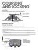
Coupling And locking Cab View Indicator Positions Showing Coupled and Locked 5th Wheel Green dot is visible at this position in guide tube Flip lock is fully seated and lynch pin is installed Follower / Indicator Rod Becomes Visible through Window Preparing VEHICLE/ trailer TO COUPLE 1. It is advised to perform trailer connections to the 5th Wheel on a firm and level surface. 2. Multiple wheel chocks should be used in front of and behind trailer tires.
Preparing 5TH wheel to Couple Refer to “Cab View” on the top of page 5 and the coupling diagram on the bottom of page 5. 1. Note that Green Dot is visible (cab side) through Lock Bar Guide Tube and Indicator Rod is visible through window. 2. Flip Safety Lynch Pin Bail and remove Lynch Pin. 3. Lift Flip Lock, rotate clockwise and let hang. 4. Pull Lock Bar to full extension (approximately 3-1/2 inches) until Jaws activate and open, then release Lock Bar. 5.
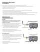
coupling If you are using a Lube Plate on the trailer kingpin, you are ready to couple the trailer to the 5th Wheel. (Up to (2) 3/16" thickness Lube Plates may be used). If you are not using a Lube Plate, apply a high pressure wheel bearing grease to the 5th Wheel Skid Plate. Never position yourself or others under the trailer’s kingpin area (DANGER ZONE) during coupling and uncoupling.
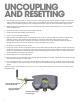
Uncoupling AND Resetting 1. When parking it may be necessary to “unload” the forces on the kingpin by lightly backing “against” the kingpin. This maneuver helps put the kingpin and 5th Wheel in a “neutral” position. Once parked on a firm and level surface, set automatic transmission vehicles to Park and activate emergency brake, set standard transmission vehicles to Neutral and activate emergency brake. 2. Multiple wheel chocks should be used in front of and behind trailer tires.
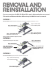
Removal And reinstallation For your convenience the Q20 5th Wheel Hitch may be disassembled to ease removal. This section will discuss the three different way the Q20 hitch can be removed.
Reinstallation Reinstall the Q20 5th Wheel in the reverse order it was removed. If removal method was per option 1, please follow the steps below: a. Place the Mid-Section still securely bolted to the legs into the Mounting Rails b. Insert the (4) Mounting Rail Pins. c. Install the (4) Hairpin Clips. d. Retorque (4) Pilot Hex Bolts to 100 ft-lb. IMPORTANT: When installing the 5th Wheel Head into the Mid-Section, the LONG END of the Bearing Shaft is inserted into the Lower Bearing Assembly.
Maintenance Requirements Years of troublefree service may be achieved by adhering to a few simple maintenance points. Jaw Pin Grease Fittings Each Jaw Pin is supplied with grease through a grease fitting located in each Jaw. These grease fittings are visible from each side of the Q20 5th Wheel. Right grease fitting Left grease fitting Lower Bearing Grease Fitting The Lower Bearing Assembly is supplied with grease through the grease fitting centered in the Cast Base Plate.
Skid Plate Greasing The last lubrication point is the Q20’s Skid Plate. Liberally apply Grease to the Skid Plate surface if NOT using a Lube Plate. A highpressure wheel bearing grease is preferred. Apply as required between coupling and uncoupling the trailer from the Q20 5th Wheel. Apply Grease to Skid Plate if NOT using Lube Plate Maintenance Schedule Lubricate before each individual use and every 1000 miles thereafter.
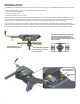
16100 & 16200 MOUNTING RAIL INSTALLATION KIT CUSTOM MOUNTING BRACKETS REQUIRED ON SOME INSTALLATIONS 09/28/06 DEALER/INSTALLER: 1) Provide this manual to end user. 2) Physically demonstrate procedure in this manual to end user. 3) Have end user demonstrate that he/she understands procedures. END USER: 1) Read and follow this manual every time you use hitch. 2) Save this manual for future reference. 3) Pass on copies of manual to any other user or owner of hitch.
G E N E R A L IN ST R U C T IO N S FO R M O U N T IN G R A IL IN ST A L L A T IO N TO O LS 3/16” drill 3/4” Socket & O pen E nd W rench 17/32” drill 100 lb-ft T orque W rench 1” drill (Som e D odge application only) “C ” C lam ps 1. T he follo wing instructions should be used to m ount the 5 th w heel. C are and attention to detail will ensure a quality installation. C heck parts against parts list to becom e fam iliar w ith parts in kit. (See Fig. 1) 2.
10. Drill two holes in frame for each bracket. Select the holes which will give the greatest spread between bolts. Install eight 1/2”-13x1-3/8” ribbed neck bolts, (thread pointing out), lock washers, and hex nuts. Tighten nuts until bolt heads seat. Lubrication of knurls of all rib neck bolts is recommended. Note: On vehicles with heavy duty suspensions, check for interference with bolts where brackets are mounted to frame.
CHEVROLET/GMC 88-98, 92-98 4-DOOR, ’99 SILVERADO SIERRA CLASSIC (WITH TAPERED FRAME) (RED TURN SIGNALS) CAUTION! Read pages 2-3 of these instructions before starting installation. Failure to do so could result in significant vehicle damage! ROW 4 ROW 3 ROW 2 ROW 1 IMPORTANT NOTES FOR THIS INSTALLATION: 1. Find parallel rows of bed sill spot welds in bed of truck. No drilling should be done in the ~4” between parallel rows of spot welds where the bed sill sits.
GM ’99 Silverado, Sierra (not Sierra Classic) models, GM ’00 to ’10 Silverado, Sierra models including HD models CAUTION! Read pages 2-3 of these instructions before starting installation. Failure to do so could result in significant vehicle damage! ROW 4 ROW 3 ROW 2 ROW 1 IMPORTANT NOTES FOR THIS INSTALLATION: 1. Find parallel rows of bed sill spot welds in bed of truck. No drilling should be done in the ~4” between parallel rows of spot welds where the bed sill sits.
GM ’11 SILVERADO CAUTION! Read pages 2-3 of these instructions before starting installation. Failure to do so could result in significant vehicle damage! ROW 4 ROW 3 ROW 2 ROW 1 IMPORTANT NOTES FOR THIS INSTALLATION: 1. Find parallel rows of bed sill spot welds in bed of truck. No drilling should be done in the ~4” between parallel rows of spot welds where the bed sill sits.
Chevrolet 73 to 87, 73 to 92 4-door (GMC) (34” Straight, with Outside Shock Absorbers) CAUTION! Drill through bed and truck frame Front of Vehicle Each mounting rail must have a bolt in either of the marked center holes. Check for obstructions before drilling. ROW 4 ROW 3 ROW 2 ROW 1 Read pages 2-3 of these instructions before starting installation.
Chevrolet 73 to 87, 73 to 92 4-door (GMC) (34” Straight, with Inside Shock Absorbers) CAUTION! ROW 4 ROW 3 ROW 2 ROW 1 Read pages 2-3 of these instructions before starting installation. Failure to do so could result in significant vehicle damage! Front of Vehicle Rear Edge of Truck Bed Each mounting rail must have a bolt in either of the marked center holes. Check for obstructions before drilling.
Ford ’97 to ’03 F-150 & F-250 8500 GVW AND UNDER and ’04 Heritage Series Body Style CAUTION! Read pages 2-3 of these instructions before starting installation. Failure to do so could result in significant vehicle damage! Front of Vehicle ROW 4 ROW 3 ROW 2 ROW 1 IMPORTANT NOTES FOR THIS INSTALLATION: 1. Long and Short Brackets on Driver’s Side may need to be switched to avoid interference with exhaust hanger. 2.
EXCEPT HERITAGE EDITION FORD ’04 AND NEWER F-150 USE 16300 BRACKET KIT CAUTION! Read pages 2-3 of these instructions before starting installation. Failure to do so could result in significant vehicle damage! IMPORTANT NOTES FOR THIS INSTALLATION: 1. Do not drill through both walls of frame. Drill only through wall of frame to which bracket is mounted. 4. When brackets are in place one of the front 2 holes should line up with a hole in the frame.
FORD F-150 & F-250 THROUGH ’96, ’97 F-250 OVER 8500 GVW, F350 THROUGH ‘97 1999 & NEWER F-250 / F-350 & f-450 SUPERDUTY (Not cab and chassis) CAUTION! Read pages 2-3 of these instructions before starting installation. Failure to do so could result in significant vehicle damage! ROW 4 ROW 3 ROW 2 ROW 1 IMPORTANT NOTES FOR THIS INSTALLATION: 1. On short bed vehicles, attach Driver’s Side forward bracket on Row 2 to avoid interference with fuel lines. 2.
DODGE ’02 TO ‘08 1500, ’03 AND NEWER 2500 WITHOUT OVERLOAD BRACKETS CAUTION! Read pages 2-3 of these instructions before starting installation. Failure to do so could result in significant vehicle damage! King Pin Centered over Axle Center Use provided tube spacer and 4 1/2" carriage bolt to attach through Bed Sill. Mounting Channel Bed Sill Front of Vehicle ROW 4 ROW 3 ROW 2 ROW 1 IMPORTANT NOTES FOR THIS INSTALLATION: 1.
DODGE ’03 AND NEWER 2500 WITH OVERLOAD SPRINGS 3500 (REQUIRES 16301 BRACKET KIT) CAUTION! Read pages 2-3 of these instructions before starting installation. Failure to do so could result in significant vehicle damage! ROW 4 ROW 3 ROW 2 ROW 1 IMPORTANT NOTES FOR THIS INSTALLATION: 1. Tube spacer and 4 ½” carriage bolt used to attach through rearward Bed Sill (Row 3). 2. **Rib neck bolts will need to be pulled through access holes in frame with supplied pull wire (see below). 3.
DODGE ’02 THRU ’08 1500 (16303 CUSTOM BRACKET KIT) 2500 WITHOUT OVERLOAD SPRINGS CAUTION! Read pages 2-3 of these instructions before starting installation. Failure to do so could result in significant vehicle damage! ROW 4 ROW 3 ROW 2 ROW 1 IMPORTANT NOTES FOR THIS INSTALLATION: 1. Tube spacer and 4 1/2” carriage bolt used to attach through rearward Bed Sill (Row 3). 2. **Rib neck bolts will need to be pulled through access holes in frame with supplied pull wire (see below). 3.
DODGE ’09 TO ’11 1500 (16305 CUSTOM BRACKET KIT) CAUTION! Read pages 2-3 of these instructions before starting installation. Failure to do so could result in significant vehicle damage! ROW 4 ROW 3 ROW 2 ROW 1 IMPORTANT NOTES FOR THIS INSTALLATION: 1. *Rib neck bolts will need to be pulled through access holes in frame with supplied pull wire (see below). 2. Observe caution note below and double check all areas prior to drilling. 3. **Do not drill thru both walls of frame.
DODGE ’94 TO ’01 1500, ’94 TO ’02 2500/3500 (FULL SIZE, SHORT AND LONG BOX) CAUTION! Read pages 2-3 of these instructions before starting installation. Failure to do so could result in significant vehicle damage! ROW 4 ROW 3 ROW 2 ROW 1 IMPORTANT NOTES FOR THIS INSTALLATION: 1. It is very important that brackets in Row 2 are against forward side of bed sill as shown below. Due to dimensional instability in bed sill placement with the Dodge truck, interference could result when drilling in Rows 3 or 4.
DODGE THROUGH 93 (FULL SIZE) CAUTION! Read pages 2-3 of these instructions before starting installation. Failure to do so could result in significant vehicle damage! ROW 4 ROW 3 ROW 2 ROW 1 IMPORTANT NOTES FOR THIS INSTALLATION: 1. You may need to move mounting rail location +/- ½” to ensure frame brackets do not interfere with bed sills. Front of Vehicle Rear Edge of Truck Bed Each mounting rail must have a bolt in either of the marked center holes. Check for obstructions before drilling.
DODGE ’94 TO 2004 DAKOTA CAUTION! Read pages 2-3 of these instructions before starting installation. Failure to do so could result in significant vehicle damage! ROW 4 ROW 3 1" Cut Off ROW 2 ROW 1 IMPORTANT NOTES FOR THIS INSTALLATION: 1. Find parallel rows of bed sill spot welds in bed of truck. No drilling should be done in the ~4” between parallel rows of spot welds where the bed sill sits. 2. Cut 1” from top flange of brackets. Under bed, mount brackets with flanges facing out. 3.
TOYOTA TUNDRA 2000 TO 2006 (STANDARD CAB LONG BOX ONLY) CAUTION! Read pages 2-3 of these instructions before starting installation. Failure to do so could result in significant vehicle damage! ROW 4 ROW 3 ROW 2 ROW 1 NOTE: For Toyota Tundra application, part #16302 spacer kit is required. Stack (1) 3/16” and (1) 5/16” thick slotted spacers as required to avoid crushing of truck bed. Front of Vehicle Rear Edge of Truck Bed Each mounting rail must have a bolt in either of the marked center holes.
TOYOTA 2007 AND NEWER TUNDRA, 6.5' & 8' BEDS, DOES NOT FIT CREWMAX CAUTION! ! ! Read pages 2-3 of 16100 instructions before starting installation. Failure to do so could reult in significant vehicle damage! IMPORTANT NOTES FOR THIS INSTALLATION: 1) Use the 16304 add-on kit with the 16100 universal kit. Read pages 1-3 of the 16100 instruction for general information. 2) The mounting holes for row 3 go through the inside of the bed sill. Make sure it lines up correctly.
NOTES FIVE YEAR LIMITED WARRANTY CURT MANUFACTURING warrants its 5 th Wheel Hitch Mounting Kits from date of purchase against defects in material and workmanship under normal use and service, for 5 years of ownership to the original purchaser when a CURT MANUFACTURING mounting kit is used. CURT MANUFACTURING will replace FREE OF CHARGE any part, which proves defective in material or workmanship when presented to any CURT MANUFACTURING dealer, CURT MANUFACTURING Warehouse or returned to the factory.