
Installation Guide

CURTMFG.COM
•
NEED ASSISTANCE?
•
877.287.8 634
•
16029-INS-RA
•
PAGE 2
Step 1
Remove the safety pin (#8) securing the
lock handles (#3, #4) in the closed position
and open the handles 90°.
Remove all four cotter pins (#9) securing the
castle nuts (#6). Loosen the castle nuts until
a minimum of 1/8" clearance between the lock
bolt (#2) and the bottom surface of the puck
(#7) is achieved.
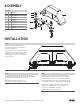
Step 2
Assemble the legs (#1) loosely to the 5th wheel head using
the M14 hardware provided with the hitch. Lower the assembly
onto the factory mount position in the truck bed.
With the hitch in position, tighten the legs
to the head by torquing the bolts to 100 ft-lbs.
Step 3
Adjust the castle nuts tension until the locking bolt (#2) is
snug when handles (#3, #4) are rotated to the lock position.
Do not over tighten the castle nuts. The handles should close
with moderate hand pressure only. Forcing the handles to the
closed position will strip the handles and result in hitch failure.
With the castle nuts adjusted to the proper height for each
lock handle, re-install the cotter pins removed in step 1.
Close all four locking handles and secure
them using the provided safety pins (#8).
1/8"
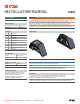
ASSEMBLY
INSTAL LATION
Parts List
Item Qty Description
1 2 Leg
2 4 Bolt, locking
3 2 Left handle
4 2 Right handle
5 4 Flat washer
6 4 Castle nut
7 4 Puck
8 2 Safety pin, 3/8" x 1-3/4"
9 4 Cotter pin
8
3
4
1
9
6
5
7
2