
Installation Guide


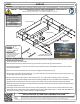
Table Of Contents

GROSS LOAD CAPACITY WHEN USED AS A WEIGHT CARRYING HITCH: LBS. TRAILER WEIGHT & LBS. TONGUE WEIGHT.
WARNING: *** DO NOT EXCEED VEHICLE MANUFACTURER'S RECOMMENDED TOWING CAPACITY ***
FOR MORE INFORMATION LOG ONTO WWW.CURTMFG.COM
HAVING INSTALLATION QUESTIONS? CALL TECHNICAL SUPPORT AT 877-287-8634
HITCH WEIGHT: LBS.
INSTALL TIME
PROFESSIONAL: MINUTES
NOVICE (DIY): MINUTES
INSTALL NOTES:
INSTALLATION STEPS
PERIODICALLY CHECK THIS RECEIVER HITCH TO ENSURE THAT ALL FASTENERS
ARE TIGHT AND THAT ALL STRUCTURAL COMPONENTS ARE SOUND.
CURT Manufacturing LLC., warrants this product to be free of defects in material and/or workmanship at the time of retail purchase by the original purchaser.
If the product is found to be defective, CURT Manufacturing LLC., may repair or replace the product, at their option, when the product is returned, prepaid,
with proof of purchase. Alteration to, misuse of, or improper installation of this product voids the warranty. CURT Manufacturing LLC.'s liability is limited to
repair or replacement of products found to be defective, and specifically excludes liability for incidental or consequential loss or damage.
This product complies with safety specifications and requirements for connecting devices and towing systems of the state of New York, V.E.S.C.Regulation V-5 and SAE J684.
5,000 750
36
60
AUDI Q5
7/28/2020
13331
120
Scan
for more
information
1. Remove (4) screws from the bottom of the bumper fascia and (2) screws from the bottom inside of the wheel well, (1) in each
wheel well, using a T25 torxbit socket.
2. Pull away wheel well lining to reveal (6) screws, (3) on each side, and remove using a T25 torxbit socket.
3. Pull away wheel well trim to reveal screw and remove using a T25 torxbit socket. Open liftgate to reveal (2) screws. Remove
using T20 torxbit socket.
4. Remove trunk floor and use plastic pry tool to remove trunk edge trim starting from the side.
5. On the inside of the trunk locate (2) rubber plugs, (1) on either side, and use the pry tool to remove plugs to access (2) nuts, (1)
on either side, and remove using 10mm socket.
6. Remove access panel on either side of trunk and locate (2) nuts, (1) on either side, and remove using a 10mm socket.
7. Gentley remove bumper fascia starting from the sides and working towards rear of car. Set aside for later reinstallation. Locate
(8) M10 bolts on the bumper beam and remove using a 16mm socket. Remove bumper beam and bumper beam bracket.
8. Raise hitch into position along with the bumper beam and bumper beam bracket and secure with hardware removed from step 7.
Torque M10 hardware to 45 ft-lbs.
9. Temporarily unhook the kick sensor wire from the clips. Using masking tape, mark out the 3.25" section in-between the center
sensor clips and trim using aviation shears. Reinstall bumper fascia to vehicle following step 7 in reverse order and reattach the
kick sensor wire. Follow steps 1-6 in reverse order to complete installation.
TOOLS REQUIRED
RATCHET
TORQUE WRENCH
6" SOCKET EXTENSION
10mm/16mm SOCKETS
T20/T25 TORXBIT SOCKETS
PANEL REMOVAL TOOL
MASKING TAPE
AVIATION SHEARS
SAFETY GLASSES
-NO DRILLING REQUIRED
-TEMPORARILY REMOVE BUMPER
FASCIA, BUMPER BEAM, AND
BUMPER BEAM BRACKET
-TRIMMING REQUIRED
TRIM DIAGRAM
BUMPER BEAM
VEHICLE FRAME
EXISTING VEHICLE
HARDWARE (BOTH SIDES)
BUMPER BEAM
BRACKET
A UPDATED HARDWARE DESCRIPTIONS/NUMBERS 7/28/2020 CJW
REVISION HISTORY
REV DESCRIPTION DATE APPROVED