
Installation Guide
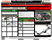
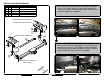
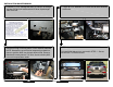
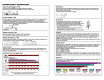
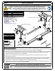
Table Of Contents

GROSS LOAD CAPACITY WHEN USED AS A WEIGHT CARRYING HITCH: LBS. TRAILER WEIGHT & LBS. TONGUE WEIGHT.
WARNING: ALL NON-TRAILER LOADS APPLIED TO THIS PRODUCT MUST BE SUPPORTED BY 18050 STABILIZING STRAPS.
WARNING: ** FAILURE TO PROPERLY SUPPORT NON-TRAILER LOADS WILL VOID PRODUCT WARRANTY **
WARNING: *** DO NOT EXCEED VEHICLE MANUFACTURER'S RECOMMENDED TOWING CAPACITY ***
FOR MORE INFORMATION LOG ONTO WWW.CURTMFG.COM & FOR HELPFUL TOWING TIPS LOG ONTO WWW.HITCHINFO.COM
HAVING INSTALLATION QUESTIONS? CALL TECHNICAL SUPPORT AT 1-877-287-8634
HITCH WEIGHT: LBS.
INSTALL TIME
PROFESSIONAL: MINUTES
NOVICE (DIY): MINUTES
INSTALL NOTES:
INSTALLATION STEPS
PERIODICALLY CHECK THIS RECEIVER HITCH TO ENSURE THAT ALL FASTENERS
ARE TIGHT AND THAT ALL STRUCTURAL COMPONENTS ARE SOUND.
CURT Manufacturing LLC., warrants this product to be free of defects in material and/or workmanship at the time of retail purchase by the original purchaser.
If the product is found to be defective, CURT Manufacturing LLC., may repair or replace the product, at their option, when the product is returned, prepaid,
with proof of purchase. Alteration to, misuse of, or improper installation of this product voids the warranty. CURT Manufacturing LLC.'s liability is limited to
repair or replacement of products found to be defective, and specifically excludes liability for incidental or consequential loss or damage.
This product complies with safety specifications and requirements for connecting devices and towing systems of the state of New York, V.E.S.C.Regulation V-5 and SAE J684.
3,500 525
27
20
BUICK ENVISION
7/31/2020
13292
40
Scan
for more
information
Parts List
DESCRIPTION
PART NUMBER
QTY
ITEM
BOLT,CAR,7/16-14 UNC,1-1/2,GRD8,YZ10-1028221
.250 x .88 x 2.25" SQUARE HOLE SPACERCM-SP222
NUT,SER-FLANGE,7/16-14 UNC,GRD8,YZ20-0010323
7/16" FISHWIRE7_16 FISHWIRE2
4
DRIVER SIDE FRAME RAIL
PASSENGER SIDE FRAME RAIL
EXISTING M10
FLANGE NUT
(BOTH SIDES)
ACCESS HOLE (BOTH SIDES)
4
1
2
3
1. Remove (2) screws holding hitch cover panel to bumper using a T15 torxbit. Remove (5) fascia tabs along hitch
cover panel using a flat head screw driver. Remove cover & save for optional re-installation.
2. Remove (2) screws holding bumper fascia using a T15 torxbit. Save screws for re-installation. Use a 15mm deep
well socket to remove (1) M10 flange nut from the bottom of driver side bumper beam attachment location &
repeat on passenger side. Save nuts for re-installation.
3. Fishwire (1) 7/16" carriage bolt and (1) CM-SP2 in through access hole and out rearmost hole in driver &
passenger side frame rail.
4. Gently pull fascia down and raise hitch into position guiding fishwires through mounting holes. NOTE: Hardware
may need to be temporarily pushed into frame to position hitch over bumper beam studs. Remove fishwires &
loosely secure 7/16 nuts. Secure existing M10 nuts onto bumper beam studs.
5. Torque all 7/16" hardware to 59 ft-lbs and all M10 hardware to 40 ft-lbs. OPTIONAL: Re-install hitch panel cover
removed in STEP 1. Secure screws with T15 torxbit socket.
- NO DRILLING REQUIRED
- FISHWIRE HARDWARE
- TEMPORARILY REMOVE HITCH
COVER PANEL
TOOLS REQUIRED
FLAT HEAD SCREW DRIVER
11/16" & 15mm SOCKETS
RATCHET
TORQUE WRENCH
T15 TORXBIT
SAFETY GLASSES