
Installation Guide
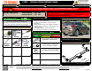
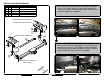
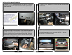
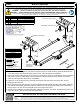
Table Of Contents

INSTALLATION WALKTHROUGH:
For more information log onto www.curtmfg.com, & for helpful towing tips log onto www.hitchinfo.com
Parts List
DESCRIPTION
PART NUMBER
QTY
ITEM
BOLT,CAR,7/16-14 UNC,1-1/2,GRD8,YZ10-1028221
.250 x .88 x 2.25" SQUARE HOLE SPACERCM-SP222
NUT,SER-FLANGE,7/16-14 UNC,GRD8,YZ
20-0010323
7/16" FISHWIRE7_16 FISHWIRE24
3
2
DRIVER SIDE FRAME RAIL
EXISTING M10 FLANGE NUT
(BOTH SIDES)
ACCESS HOLE (BOTH SIDES)
4
PASSENGER SIDE FRAME RAIL
1. Remove (2) screws holding hitch cover panel to bumper
using a T15 torxbit. Remove (5) fascia tabs along hitch
cover panel using a flat head screw driver. Remove cover
& save for optional re-installation.
2. Remove (2) screws holding bumper fascia using a T15
torxbit. Save screws for re-installation. Use a 15mm deep
well socket to remove (1) M10 flange nut from the bottom
of driver side bumper beam attachment location & repeat
on passenger side. Save nuts for re-installation.
1