
Installation Guide

GROSS LOAD CAPACITY WHEN USED AS A WEIGHT CARRYING HITCH: LBS. TRAILER WEIGHT & LBS. TONGUE WEIGHT.
GROSS LOAD CAPACITY WHEN USED AS A WEIGHT DISTRIBUTION HITCH: LBS. TRAILER WEIGHT & LBS. TONGUE WEIGHT
***DO NOT EXCEED VEHICLE MANUFACTURER'S RECOMMENDED TOWING CAPACITY.***
HAVING INSTALLATION QUESTIONS? CALL TECHNICAL SUPPORT AT 877-287-8634
PERIODICALLY CHECK THIS RECEIVER HITCH TO ENSURE THAT ALL FASTENERS
ARE TIGHT AND THAT ALL STRUCTURAL COMPONENTS ARE SOUND.
Curt Manufacturing Inc., warrants this product to be free of defects in material and/or workmanship at the time of retail purchase by the original purchaser. If the product is found to be defective,
Curt Manufacturing Inc., may repair or replace the product, at their option, when the product is returned, prepaid, with proof of purchase. Alteration to, misuse of, or improper installation of
this product voids the warranty. Curt Manufacturing Inc.'s liability is limited to repair or replacement of products found to be defective, and specifically excludes liability for incidental or
consequential loss or damage.
4,000 400
4,500
450
VOLVO XC60
7/27/2020
13268
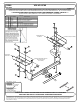
INSTALLATION STEPS
INSTALLED HITCH POSITION
FASCIA
Note: On 2015 and newer vehicles with dual exhaust, remove the screws attaching the decorative exhaust ports
in the fascia using a T15 Torx socket.
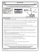
1. Lower exhaust by removing rubber isolator(s) from muffler(s). (See RUBBER ISOLATOR REMOVAL DIAGRAM.)
2. Remove exhaust hanger for ease of heat shield trimming. Save exhaust hanger for reinstallation in Step 14.
3. Trim heat shields (one per side) to provide clearance around hitch side plates.
4. Remove tape covering holes on bottom and sides of each frame rail. Save tape for reuse in Step 13.
5. Fishwire 7/16-14 x 1 1/2" carriage bolts and CM-SP11 spacers through access hole in frame rails and out middle
mounting hole for hitch. (See FISHWIRE TECHNIQUE diagram.)
6. Raise hitch into position over exhaust and secure hitch with hand tightened 7/16" hex flange nuts, as shown.
7. Slide CM-SP52 spacers into position between hitch side plates and frame rails for front mounting holes, as
shown.
8. Fishwire 7/16-14 x 2" carriage bolts and CM-SP7 spacers through access holes and out front mounting holes,
as shown. (See FISHWIRE TECHNIQUE diagram.)
9. Install hand tightened 7/16" hex flange nuts onto hardware from Step 8.
10. Fishwire 7/16-14 x 2" carriage bolts and CM-SP7 spacer through rear of frame rails and out mounting holes on
sides of rails, as shown. (See FISHWIRE TECHNIQUE diagram.)
11. Install hand tightened 7/16" hex flange nuts onto hardware from Step 10.
12. Torque 7/16" hardware to 70 lb-ft.
13. Cut tape removed in Step 4 into strips to cover unused holes exposed in frame rails.
14. Reinstall exhaust hanger removed in Step 2.
15. Raise exhaust back into position and reinstall rubber isolators (removed in Step 1) and decorative exhaust ports
if removed.
PAGE 2 of 2
1
CHG TO GRADE 8 TORQUE SPECS
9/28/2012
AJP
2 ADDED NOTE IN INSTALL STEPS FOR 2015 NEWER W/DUAL EXHAUST 12/22/2014 KWS
3
DELETED THE SPECIFIC NUMBER OF FASTNERS TO BE REMOVED 9/14/2015 DAM
4 UPDATED HARDWARE DESCRIPTIONS/NUMBERS 7/27/2020 CJW
REVISION HISTORY
REV DESCRIPTION DATE APPROVED
TOOLS REQUIRED
SOCKET WRENCH
11/16" SOCKET
13mm SOCKET
T15 TORX SOCKET
TORQUE WRENCH
AVIATION SHEARS