
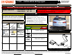
Owners manual
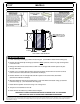

HEAT SHIELD TRIM DIAGRAM
HAVING INSTALLATION QUESTIONS? CALL TECHNICAL SUPPORT AT 1-800-798-0813
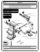
INSTALLATION STEPS
PERIODICALLY CHECK THIS RECEIVER HITCH TO ENSURE THAT ALL FASTENERS
ARE TIGHT AND THAT ALL STRUCTURAL COMPONENTS ARE SOUND.
Curt Manufacturing LLC, warrants this product to be free of defects in material and/or workmanship at the time of retail purchase by the original purchaser. If the product is found to be defective,
Curt Manufacturing LLC, may repair or replace the product, at their option, when the product is returned, prepaid, with proof of purchase. Alteration to, misuse of, or improper installation of
this product voids the warranty. Curt Manufacturing LLC's liability is limited to repair or replacement of products found to be defective, and specifically excludes liability for incidental or
consequential loss or damage.
MAZDA 5
11127
PAGE 2 of 2
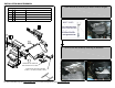
1. Lower exhaust by removing (3) rubber exhaust hangers. (See Rubber Isolator Removal Diargram)
2. Remove the heat shield by removing (6) fasteners. Note: If present, remove any tape covering holes
in the frame rails.
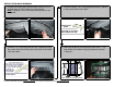
3. Enlarge the forward most access holes to allow 7/16-14 carriage bolts and SP7 spacers to pass
through, both sides.
4. Fishwire 7/16-14 carriage bolts and SP7 spacers through the access holes and out the rear-most
holes in the frame rails, both sides. (See Fishwire Technique)
5. Reverse fishwire 7/16-14 carriage bolts and SP7 spacers in the access holes, both sides.
(See Reverse Fishwire Technique)
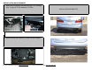
6. Mark heat shield for trimming and confirm the fit. Trim heat shield and reattach using (4) fasteners
removed in Step (2). (See Heat Shield Trim Diagram)
7. Raise hitch into position and secure using 7/16-14 flange nuts.
8. Torque all 7/16" hardware to 70 ft-lbs.
9. Raise exhaust and reattach (3) rubber exhaust hangers.
13.00 in
1.00 in 10.00 in
NOTE: DIMENSIONS ARE
APPROXIMATE, CONFIRM
FIT PRIOR TO TRIMMING