
Product Manual


PAGE 7
•
51170-INS-RB
•
800.798.0813
•
NEED ASSISTANCE?
•
CURTMFG.COM
1. Determine a suitable mounting location for the main module.
a. The unit must be mounted securely to a solid surface,
preferably under the dash (Fig 1).
b. The unit needs to be connected to the LED display rotary knob.
MOUNTING THE MAIN MODULE
2.
See the '
Wiring the Plug Connector to the LED Display Knob
' section
(page 6) before continuing
the installation. Insert the plug connector
attached to the LED display rotary knob into the main module.
3. See the 'Set Manual Control Output and Brake Light Switches'
section (page 11) before mounting the main module.
4. Once the LED display rotary knob is connected, secure the main module
in place using the provided main module adhesive pad and / or zip-ties.
5. Plug in the main module to the pigtail harness or vehicle-specific
quick plug. If harness is unavailable, hard wiring will be necessary.
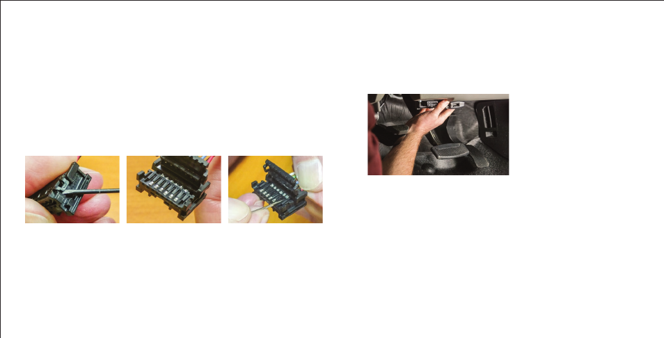
Figure 1
Figure 1 Figure 2 Figure 3
UNINSTALLING THE BRAKE CONTROL
If you wish to uninstall the brake control, the plug connector attached to
the LED display knob can be unpinned without cutting the interface cable.
Using a small flat head screw driver unlatch the two locking tabs
securing the locking mechanism in place (Fig 1). Once the two locking
tabs are unlatched the locking mechanism can open (Fig 2).
With the locking mechanism open, use a pin to gently pry up the plastic
tab securing the terminal in place while gently pulling on the wire (Fig 3).
Repeat for all six terminals attached to the plug connector. Once all of
the terminals are free the brake control can be removed from the vehicle.