
Product Manual


CURTMFG.COM
•
NEED ASSISTANCE?
•
800.798.0813
•
51170-INS-RB
•
PAGE 6
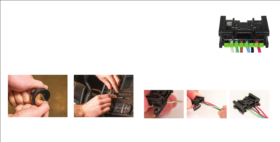
WIRING THE PLUG CONNECTOR TO THE LED DISPLAY KNOB
While holding the plug connector with the locking mechanism facing
downward insert the terminals into the connector with the folded
metal crimp facing down (Fig 2). As each terminal is fully inserted, it
will 'click' into place and the terminal will not pull out. When all six
terminals are inserted into the plug connector and fully seated, close
and latch the locking mechanism (Fig 3 and Fig 4).
Refer to the plug connector image
(Fig 1) for the below wire locations.
Note: Keep positions 1 and 8 empty.
Figure 1
87654321
1. No wire
2. White
3. Green
4. Brown
5. Blue
6. Black
7. Red
8. No wire
MOUNTING THE LED DISPLAY ROTARY KNOB - CONTINUED
Base plate installation, surface adhesive mount option
1. Determine a suitable mounting location for the LED display knob.
a. The LED display must be mounted securely to a solid surface.
b. The LED display must be easily reached by the driver.
2. Place the base plate adhesive pad onto the base plate and adhere
the base plate onto the dash in any of the four orientations (Fig 5).
3. Insert the LED display rotary knob into the base plate with the LEDs
in the upright position. Press down until you hear a 'click' (Fig 6).
4. Route the cable coming from the LED display knob to the main module.
See the 'Main Module' section (page 7).
Figure 6Figure 5
Figure 2 Figure 3 Figure 4