
Product Manual


CURTMFG.COM
•
NEED ASSISTANCE?
•
800.798.0813
•
51170-INS-RB
•
PAGE 2
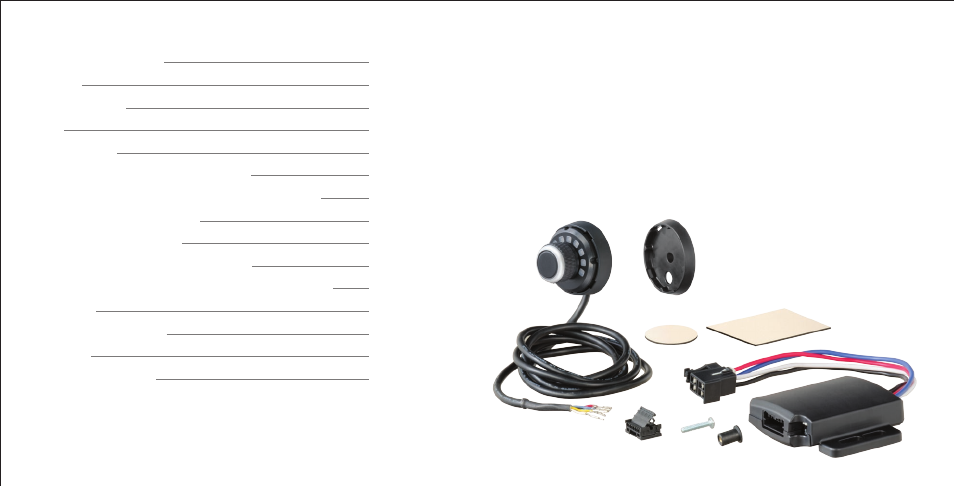
1. Main module
2. Main module adhesive pad
3. LED display rotary knob
4. Plug connector for LED display
5. Base plate
6. Base plate adhesive pad
7. Well-nut
8. Screw, #6 - 32
Controls & Components
Tools List
Before You Begin
Wiring
Wiring Diagram
Mounting the LED Display Rotary Knob
Wiring the Plug Connector to the LED Display Knob
Uninstalling the Brake Control
Mounting the Main Module
Modes & Indicators on the LED Display
Set Manual Control Output and Brake Light Switches
Initial Setup
Test Drive & Adjustment
Bench Test
Troubleshooting Guide
page 2
page 2
page 3
page 3
page 4
page 5
page 6
page 7
page 7
page 8
page 11
page 11
page 12
page 12
page 14
1. Drill
2. Drill bit, 5/16"
3. Phillips screwdriver
4. Pry tool
CONTROLS & COMPONENTSTABLE OF CONTENTS
TOOLS LIST
6
2
1
5
4
3
7
8