
Product Manual


PAGE 13
•
51170-INS-RB
•
800.798.0813
•
NEED ASSISTANCE?
•
CURTMFG.COM
BENCH TEST - CONTINUED
Go to the output setting and rotate the LED display knob clockwise to
its maximum setting. Go to the sensitivity settings and rotate the knob
clockwise to its most aggressive setting. Activate the manual control up
to its full output. While actuating the manual control the brightness of the
bulb will correspond with the output shown by the brake control. Release
the manual control to deactivate.
While keeping the brake control level, connect the red brake input
wire of the main module to the positive terminal of the 12V battery.
The brake control output will activate and the bulb may be dimly lit.
Slowly tilt the main module to about 45° and the brightness of the bulb
will increase corresponding with the output shown by the brake control.
Slowly tilt the main module back to level and the brightness of the bulb
will decrease, corresponding with the output shown by the brake control.
Manual Control Testing
Accelerometer Testing
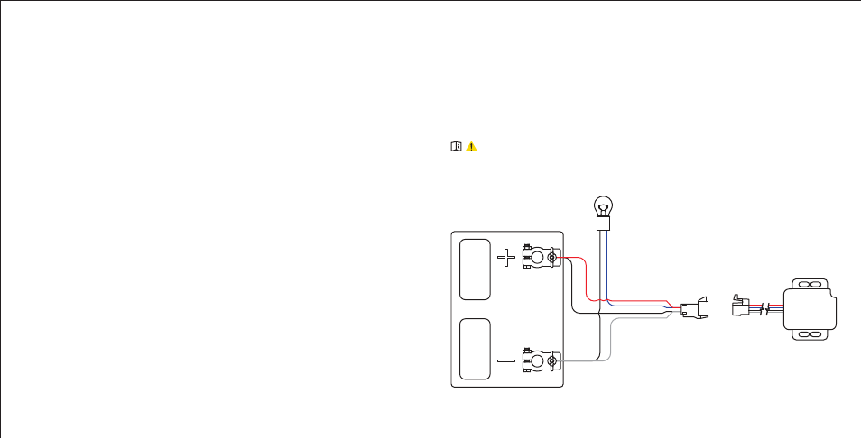
IMPORTANT: Read and follow all
warnings and cautions shown on the battery.
RED: BRAKE SIGNAL
Connect red wire when
testing accelerometer.
BLUE: BRAKE OUTPUT
Connect after the unit is powered.
Reconnect if required during recalibration.
Standard 1156 automotive
bulb in lamp socket.
BLACK: BATTERY
#51515 / #51516:
QUICK PLUG
WHITE: GROUND
Ensure the Spectrum
™
is level to the bench surface and connect the
signal wire of the bulb to the blue brake output wire of the Spectrum
™
.
The LED display will ramp-up green to indicate it is checking calibration.
This ensures power to the Spectrum
™
, and you can proceed to test
manual control and accelerometer.
After testing, disconnect the wiring from the positive terminal
of the 12V battery ensuring the exposed contacts do not make contact.
If the Spectrum
™
does not function as described during the above test
steps, return the brake control for service or replacement.
Brake Control Setup - continued