
Product Manual

Curt Manufacturing Inc., warrants this product to be free of defects in material and/or workmanship at the time of retail purchase by the original purchaser. If the product is found to be defective,
Curt Manufacturing Inc., may repair or replace the product, at their option, when the product is returned, prepaid, with proof of purchase. Alteration to, misuse of, or improper installation of
this product voids the warranty. Curt Manufacturing Inc.'s liability is limited to repair or replacement of products found to be defective, and specifically excludes liability for incidental or
consequential loss or damage.
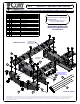
16418 CHEVROLET / GMC SHORT AND LONG BOX
!WARNING!
- Do not install mounting rails over plastic bed liners. Plastic liners must be trimmed for metal-to-metal contact. May be installed on spray in liner.
- Use only supplied fasteners for installation.
- Before installing hitch measure to be sure there will be enough clearance between the truck and trailer to allow for turns.
1) Lower and remove spare tire. Remove exhaust heat shield.
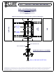
2) Place the front mounting rail in the box of the truck, using your tape measure, center the rail on the truck box floor
and the proper distance from the rear edge of the truck box as shown on the "rail location diagram" page.
NOTE: All measurements are from rear edge of truck box, NOT tailgate.
3) Using a center punch, mark the holes as per the rail location diagram. Move the mounting rail out of the way and
drill each position with a 1/8" drill bit.
4) Temporarily position the frame bracket on the side of the frame and check that the 1/8" drilled holes align with the
slots of the frame bracket. Remove the frame bracket from the vehicle.
5) Enlarge the 1/8" drill holes to the 9/16" with a step drill.
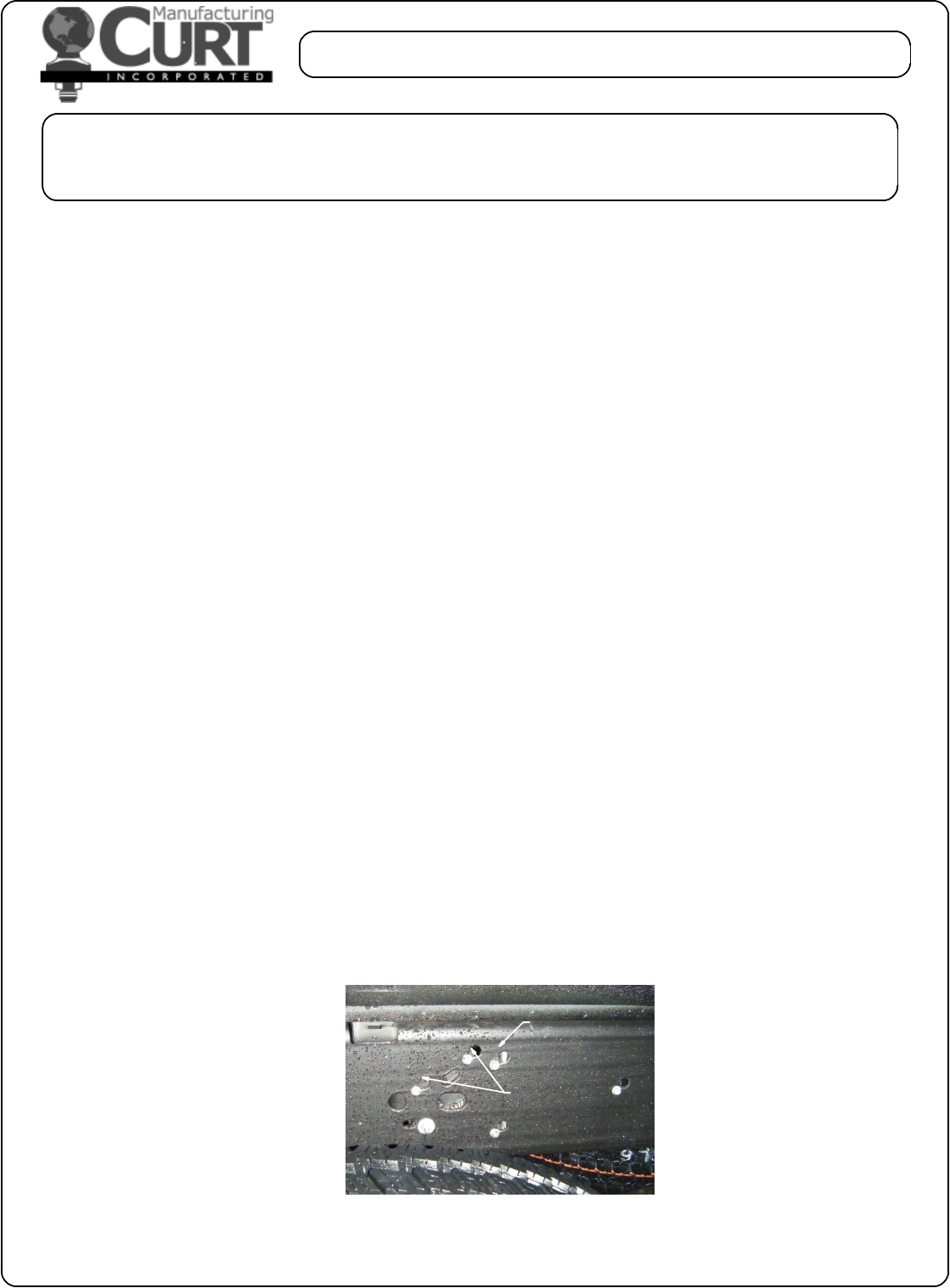
6) Fasten the frame bracket to the side of the frame using the appropriate hardware. For 2500 & 3500 07' and
up new body styles, remove the front electical box on the inside of the driver side frame and attach
it to the supplied bracket. Remove upper most fastener on the rear electrical box and return to owner,
see photo below. A bolt leader will be required to install the front hardware as access to the hole is restricted.
Tighten hand tight.
NOTE: On long box models, DO NOT drill the front hole at this time.
7) Reposition the mounting rail over the holes and fasten the mounting rail to the frame brackets using the supplied
carriage bolts. Use the supplied spacers between the frame bracket or mounting rails and the truck box so as to
ensure a metal to metal contact.
8) Place the unassembled 5th wheel / roller / gooseneck hitch into the already installed mounting rail. Position the
second mounting rail with the 5th wheel / roller / gooseneck hitch by iserting the tabs into the mounting rail and
pushing the mounting rail tight towards the other mounting rail. Ensure that the mounting rail is centered on the
truck box floor. This will position the rail in the correct location and ensure that the 5th wheel will have a snug fit
to the truck.
NOTE: If more than one hitch product will be used with the mounting rails then both should be used at
the same time to align the second mounting rail. This will ensure that one product does not
compromise the fit of the other.
9) Repeat steps 3, 5 and 7
10) On long box models, use the frame bracket as a guide to drill the front 1/2" hole through the frame. A bolt
leader will be required to install the front hardware as access to the hole is restricted. Tighten hand tight.
11) Starting with the carriage bolts that fasten the rails to the frame bracket, torque all the nuts. Torque all 1/2"
fasteners to 110 lb-ft and all 3/4" fasteners to 380 lb-ft.
12) Re-install spare tire.
REMOVE FASTENER AND
RETURN TO OWNER
FASTENERS USED TO
RELOCATE ELECTRICAL
BOX TO SUPPLIED BRACKET
ELECTRICAL BOX RELOCATION