
Product Manual
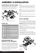

Step 1
Locate the handle assemble and hardware pack provided
with your A25 5th wheel hitch as shown on the front page.
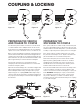
WARNING: The jaws on the 16180 head are spring loaded.
The jaws will open rapidly when the safety pin is removed
and the handle is moved to the unlock position. Keep hands
clear of the jaws at all time.
Step 2
Slide the handle assembly over the end of the
handle mount bar on the A25 head as shown below.
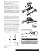
Step 3
Insert the latch spring into the slot on the handle mount bar
and then continue sliding the handle assembly into place.
Step 4
Position the handle assembly so the first M8 bolt
and lock washer can be dropped into position
behind the latch spring as shown below.
Step 5
With the first M8 bolt in place behind the latch spring, pull the
handle assembly back out until the second M8 bolt and lock
washer can be dropped into position.
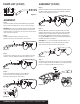
Step 6
With both M8 bolts in place through the handle assembly,
slide the latch plate into position and secure it by threading
the M8 bolts into the tapped holes. Alternate between the
two bolts while tightening. Evenly draw the latch plate up to
the handle. NOTE: Pulling out on the handle while tightening
the M8 bolts will ease installation.
CAUTION: Do not crush the handle assembly tube by over
tightening the M8 bolts. The handle assembly must slide
freely over the handle mount bar to latch properly.
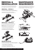
Step 7
Confirm the lock bar latches into position as shown in Detail B
below. Complete the handle installation by inserting the safety
lynch pin, locking the handle in the tow position.
ASS E MBLY
Figure 7
Figure 11
Figure 12
Figure 10
Figure 8
B
Detail B
9
4
4
4
7
7
4
6
8
6
7
5
PARTS LIST
(
CONT
)
AS S E MBLY
(
CONT
)
Figure 6
Figure 9
A
Detail A
6
8
87
5
6
9
4
CURTMFG.COM • NEED ASSISTANCE? • 1.800.798.0813 • 16180-INS-RA • PAGE 4