
Product Manual

A
Figure 4
Figure 5
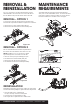
NOTE: The head assembly can easily be removed from the
midsection to further aid installation of the hardware.
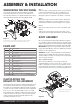
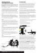
Step 2 - Mount to the Base Rails
Before attaching your A25 to the tow vehicle's mounting
rails, check the base rails in your truck to be sure they are
properly installed and are parallel with each other. The
diagonal dimensions should be the same, see Figure 3.
With the base rails correctly positioned, the A25 5th wheel
assembly will drop into the slots on the top surface of the
base rails. Align the four tabs on the bottom of the A25 legs
with the corresponding slots in the tow vehicles mounting
rails. Lower the 5th wheel assembly into the rails. Secure the
5th wheel by installing the four 1/2" rail mount pins & clips as
illustrated in Figures 4 and 5. NOTE: You may find it easier
to position the A25 assembly and lower it into the rails with
the center head section removed to reduce weight.
If installing new bed mounting rails, follow the instructions
provided by the rail manufacturer for proper placement,
alignment and spacing per your vehicles year, make and
model. If the A25 5th wheel is being mounted to existing
bed mounting rails, and alignment issues arise, it may be
necessary to proceed as follows:
Loosely assemble the legs to the A25 5th wheel mid-section.
Place the unit on top of the existing bed mounting rails,
aligning the foot tabs with the outermost rectangular slots of
the mounting rails. When the 5th wheel foot tabs drop into
the four rectangular slots, pin the foot tabs using the four
pins & clips provided. Continue assembly by tightening the
pilot hex bolts to 100 foot lbs. If difficulty is still experienced
fitting the A25 5th wheel into the existing bed mounting
rails, it may be necessary to loosen the mounting rail bolts
and realign the mounting rails to facilitate installation. It is
recommended to replace old lock washers with new lock
washers at this time. Torque mounting rail bolts to the
rail manufacturer's specifications. Continue with the A25
installation by tightening the bolts to 100 foot lbs.
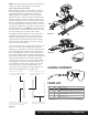
Ensure rail kits are installed
according to rail kit manufacturer's
recommended specifications
Front of truck
Rear edge of truck bed
Rear edge of truck bed to
rear edge of mounting rail
Measure diagonal from same
reference point. Measurement
should be the same
Each mounting rail must have a bolt
in either of the marked holes. Check
for obstructions before drilling
Figure 3
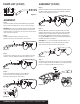
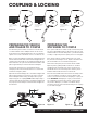
HANDLE ASSEMBLY
Item# Qty Description
4 1 Handle assembly
5 1 Handle lock bar
6 2 Button head cap screw, M8 - 1 1/2" x 30
7 2 Lock washer, M8
8 1 Latch spring
9 1 Safety latch pin, 3/8"
PARTS LIST
A
Detail A
PAGE 3 • 16180-INS-RA • 1.800.798.0813 • NEED ASSISTANCE? • CURTMFG.COM