
Product Manual

11
13
15
14
3
1
2
5
6
4
8
9
10
12
7
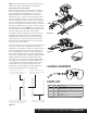
PARTS LIST
CALCULATING THE
HEIGHT OF THE ASSEMBLY
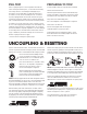
UNPACKING THE 5TH WHEEL
Item# Qty Description
1 1 16180 body and head assembly
2 1 Leg weldment
3 1 Leg weldment - driver side with instruction label
4 1 Handle assembly
5 1 Handle lock bar
6 2 Button head cap screw, M8 - 1.25" x 30
7 2 Lock washer, M8
8 1 Latch spring
9 1 Safety latch pin, 3/8"
10 4 Hex bolt, M14
11 4 Lock washer, 14mm
12 4 Flat washer, 14mm
13 4 Nylock nut, M14
14 4 Base rail mounting clip
15 4 Base rail mounting pin, 1/2" diameter
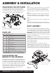
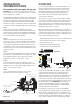
Assembly includes measuring the height requirement for the
A25 5th wheel head in relation to your trailer ride height at
the kingpin box and skid plate. Ideally the trailer should ride
as near to level as possible. The A25 5th wheel is adjustable
from 13" to 17", from the pickup bed to the top of its skid
plate. Adjustment is attained by adjusting the mid-section up
or down, in relation to the legs, in 1.25" increments (typical
clearance between the pickup bed rails and the trailer
should be a minimum of 5 1/2").
Your A25 5th wheel hitch has been partially assembled,
inspected and tested for fit, function and completeness.
The A25 5th wheel hitch is an engineered unit that has been
designed and tested at the rating of 25,000 lbs. GTW.
Be sure that the leg with the warning and instruction labels
is placed on the side of the unit with the activation bar.
Figure 1
Figure 2
ASSEMBLY & INSTALLATION
Once you have determined the height adjustment required
for your A25 5th wheel, assemble the legs to the mid-section
using the appropriate holes. Occasionally, the trailer's kingpin
'pin box' will require adjustment to facilitate correct ride height.
IMPORTANT: Torque the four pilot bolts to 100 foot lbs. Re-
torque after initial 500 miles and every 1,000 miles thereafter
and prior to each individual use.
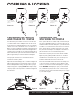
WARNING: The jaws on the 16180 head are spring loaded.
The jaws will open rapidly when the safety pin is removed
and the handle is moved to the unlock position. Keep hands
clear of the jaws at all time.
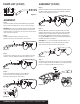
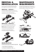
Step 1 - Attach the Legs
Attach the leg weldments to the mid-section with the
supplied hardware, 'Parts List' items 10, 11, 12 and 13. See
Figure 1. Depending on which holes are required to achieve
proper ride height, attachment of the legs to the mid-section
may be easier with the mid-section positioned upside-down.
BODY ASSEMBLY
Step 1
With your trailer on a firm and level surface, set chock blocks
in front of and behind the tires. (Do not substitute wood
blocks, rocks, etc. for chock blocks.) Extend front trailer
lifting jacks, adjust as required to set trailer at or near level.
Step 2
Measure from the ground to under the trailer's kingpin box
skid plate (or lube plate if used). This will be the portion in
contact with the A25 5th wheel's skid plate once coupled.
Step 3
Measure from the ground to the surface of the pickup bed.
Step 4
Subtract the measurement from Step 2 from Step 1. This
value will be near the height requirement for the A25 5th wheel.
Torque 14mm pilot hex bolts
to 100 foot lbs. TYP(X4)
11
10
13
12
CURTMFG.COM • NEED ASSISTANCE? • 1.800.798.0813 • 16180-INS-RA • PAGE 2