
Technical data

4. Link the apparatus symbols with line elements.
5. Adjust the text symbols while writing to north, east, south or west. Use the object
property window to do it.
6. Place measurements when needed.
7. Edit the name, unit and number of decimals of the measurements.
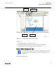
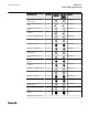
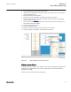
8. Select each object that has a dynamic link and do the link to the corresponding
process object, see
Figure 56.
9. Check to select the correct function block. Function blocks of the same type can
have different instance numbers.
10. Validate that all links are done.
11. Save the complete picture.
12. Repeat the steps for all pages when more than one is needed.
13. Write the display configuration to IED from the GDE tool.
IEC09000666-1-en.vsd
IEC09000666 V1 EN
Figure 56: GDE: Establish a dynamic object link
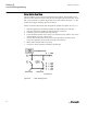
Linking process objects
To describe a process object within an IED it needs to be established in the application
configuration, configured when given with its parameters by PST and linked to be
displayed in the HMI.
Three tools are involved for the described steps:
1MRK 511 261-UUS A Section 6
Local HMI engineering
650 series ANSI 93
Engineering Manual