
Technical data
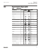
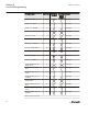
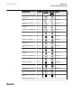

IEC Symbol Name Node Type IEC Symbol
Definitions
ANSI Y32.2/
IEEE 315
Symbol
Definitions
Category
Breaker2 indication only, 11 =
Undefined
35 Switchgear
Static text 0 Texts
Dynamic text 29 Texts
Select button, 00 = Middle
position
30 Texts
Select button, 01 = Open 30 Texts
Select button, 10 = Closed 30 Texts
Select button, 11 = Undefined 30 Texts
Indication button, 00 = Middle
position
31 Texts
Indication button, 01 = Open 31 Texts
Indication button, 10 = Closed 31 Texts
Indication button, 11 = Undefined 31 Texts
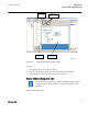
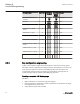
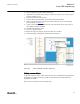
6.2.3 Bay configuration engineering
A page with a single line diagram and measurements contains active living objects.
The object values are updated by the IED periodically (measurement) or in case of an
event. Once the symbols are placed on the HMI page they must be linked to the
corresponding function block in the application configuration, which protects or
controls the object that the symbol on the HMI page represents.
Creating a complete HMI display page
Procedure:
1. Make a sketch how to present the single line diagram.
2. Place the apparatus, transformer and other symbols that are needed for the single
line diagram into the raster boxes.
3. Add connection points where needed.
Section 6 1MRK 511 261-UUS A
Local HMI engineering
92 650 series ANSI
Engineering Manual