
Technical data

Doing Link to draw lines
The line width has to fit to the line width used for the symbols. The standard size is 2.
Choose the line width in a selection box placed in the upper area above the page. A line
that is not connected to a symbol may be done in any line width in the range 1 - 5. But
it needs to be simple connection points to be drawn.
For the procedure to draw lines when the apparatus symbols are placed, see
Figure 55.
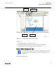
1. Place the apparatus or transformer symbols by drag and drop in a raster box.
2. Place the connections symbols by drag and drop in a raster box.
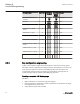
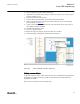
3. Click the Link icon to enable direct line drawing.
4. Center the mouse pointer on the center of a connection point; visible in two circles
at the endpoints of a line, to draw a line.
5. Click to start and move the mouse pointer to the destination connection point.
Center once again the mouse pointer and click to drop the line.
6. Draw all line elements that are necessary.
7. Click Select in the menu bar to finish the line drawing.
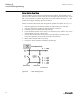
en05000598.vsd
start point end point
Line draw icon
IEC05000598 V1 EN
Figure 55: GDE: Drawing a line
Section 6 1MRK 511 261-UUS A
Local HMI engineering
88 650 series ANSI
Engineering Manual