
Technical data

• Several single line diagrams can be created for one bay.
• The IED supports one bay.
• The sequence order of the HMI pages in the Graphical Display Editor starts from
left to right.
• Measurements and the single line diagram can be shown on the page in any
possible order and placement.
• All symbol objects, for example apparatus, text and measurement, on the HMI
page must be linked to the correct function block in the application configuration
in order to present the correct process values.
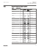
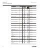
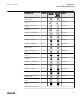
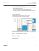
Symbol library
The symbol library window contains some panes that include drawing symbols or
elements to create a single line diagram, measurements and texts on a page. Click on
the name bar of the selected element to open the pane.
The library shows the symbols either in ANSI standard or in IEC standard. The
standard is selected by the drop down list box located on top of the display window.
When changing to the other library standard, GDE closes the library windows, changes
the symbols according to the selected new standard and redraws the single line diagram
in the display window.
Select the different panes and their symbols to become familiar with the available
symbols.
Measurements (Measurands) are presented in one format that explains itself when
selected. Select the format and drop it in the drawing area. Use the object properties to
make adaptations.
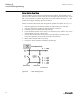
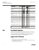
Special symbols for dynamic text
In the text pane the symbol library contains a set of special symbols to present text that
depends on the status of variables. A set of three symbols is either valid for a single bit
information or for a list of up to 32 different inputs. The corresponding function blocks
in ACT are of type xxxGGIO.
• Select Dynamic Text and Indication to present the text for the actual value of the
function block, see
Figure 54.
• Click Select Button to select the value.
Section 6 1MRK 511 261-UUS A
Local HMI engineering
86 650 series ANSI
Engineering Manual