
Technical data


IEC08000258.vsd
1
3
7 8 9
17
16
12
11
10
2
5 6
1514
13
4
IEC08000258 V1 EN
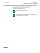
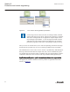
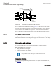
Figure 32: ACT: Function block overview
1 Connection(s)
2 User defined function block name
3 Function block, selected (red)
4 Mandatory signal (indicated by a red triangle if not connected)
5 Function block name
6 Function block, locked (red)
7 ANSI symbol
8 Inverted output
9 Hardware, binary output channel
10 Hardware, analog input channel
11 User defined signal name
12 Hardware, binary input channel
13 Execution order
14 Cycle time
15 Instance number
16 Inverted input
17 Signal description note
5.1.3 Signals and signal management
A function block has set of input and output signals. The placement of the signals for a
function block is from left to right. Input signals are placed on the left side and output
signals are placed on the right side.
Section 5 1MRK 511 261-UUS A
Protection and control engineering
60 650 series ANSI
Engineering Manual