
Installation Guide


Product Specifications
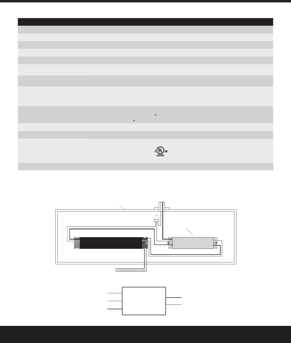
Wiring Diagrams
Installation Guide
2
Type 1.B action Pollution degree 2 Rated Impulse voltage 4000V
(N) Input White
(L) Input Black
(L) Relay Output Red
(-) 0-10V GND Grey
(+) 0-10V OUT Purple
0-10V LED Driver
Driver Line (L)
Driver Neutral (N)
Wire Nut
(N) (L)
Driver 0-10V Dimming Wires
Driver LED Output Wires
(to LED Array)
(+)
(-)
Fixture Mains
(via code-compliant conduit)
Fixture Driver Housing
(or code-compliant wiring box)
(+)
(-)
The interface and wiring is intended to be installed and
completely enclosed within the same NEC Class 1 driver
housing as the 0-10V driver using metal mounting
(Relay Output)
(L)
(N)
(Relay Output)
(N) (L)
screws(not provided).
10 years
UL 60730-1/1310+FCC Part 15,Subpart B,Class B
-25C to +50C
Dim Level - 0-10V Dimming Voltage Level
On/Off - Relay Status
Certification
Operating Ambient Temperature
Warranty
Function
Loading
Output Power
Connectivity
Wire Size
Size
Housing
Relay Contact
Input power
Characteristic
120-277VAC 50/60HZ,Maximum 3A
120-277VAC 50/60HZ,Maximum 3A
White
0-10 UL/NEC Class 2 protected 0-10V dimming,Maximum 32mA
24-14AWG,Solid or Tinned-Stranded Copper for P2 terminal
7.08“lxl.38”wx0.93”h(180*35*23.5mm)
E486320
FCC ID: 2AS3F-WGZ100
IC: 25008-WGZ100
Miscellaneous Controls
SKU
95041200
UltraMax
®
Parameter
Translates Daintree® Networked messages to control electronic ballast or LED driver
WGZ100
Left : (N)Input (L)Input (L)Relay Output
Right : 0-10V GND 0-10V OUT
1) 120-277V, 3A, General Use
2) 120-277V, 3A, Electronic Ballast or LED Driver
Interface to use Daintree® Networked
with 0-10V devices (WGZ100)