
Installation Guide


Installation Guide
BEFORE YOU BEGIN
Read these instructions completely and carefully.
WARNING / AVERTISSEMENT
•
•
•
•
•
•
•
•
•
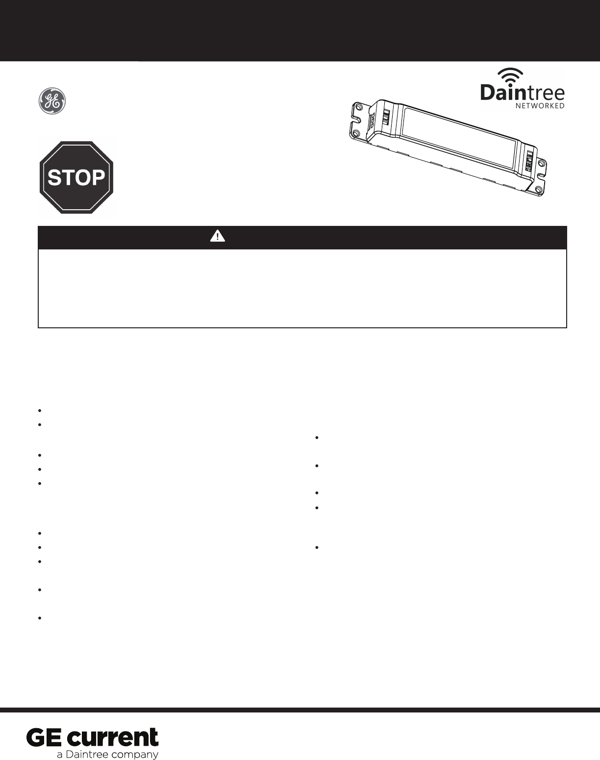
UltraMax
Turn power off before inspection, installation or removal.
Properly ground electrical enclosure.
Follow all NEC and local codes.
Use only UL approved wire for input/output connections.
Minimum size 14 AWG for continuous runs.
Coupez l'alimentation avant d'inspecter, installer ou déplacer le luminaire.
Assurez-vous de correctement mettre à la terre le boitier d'alimentation électrique.
Respectez tous les codes NEC et codes locaux.
N'utilisez que des fils approuvés par UL pour les entrées / sorties de
RISK OF ELECTRIC SHOCK
RISK OF ELECTRIC SHOCK
RISQUES DE DÉCHARGES ÉLECTRIQUES
RISQUES D'INCENDIE
Use only in the manner intended by the manufacturer. If you have any questions, contact the manufacturer.
Save These Instructions
Installation to be performed by factory trained or
qualified personnel
This device is designed for field wiring in a suitable
junction box in accordance with applicable codes
Provide suitable enclosure for outdoor use
Use this product only in the manner intended by
the manufacturer. If there are any questions or
concerns, contact the manufacturer
This device complies with FCC Part 15 Subpart B
Class B
For Your Safety
Read and observe all WARNINGS shown
throughout these instructions
Wire nuts
Equipment necessary for luminaire disassembly
Wire stripper/cutter
Installation Guide
Tools and Parts Required
Installation Procedure and Troubleshooting
Follow wiring diagram provided
Secure interface within suitable enclosure
Connect Interface Line (L) and Neutral (N) to
input power
Connect Relay Output to driver input Line and
Connect Driver Neutral to input power Neutral
If the device does not perform in the expected
manner, do not attempt to repair, contact the
manufacturer.
WGZ100
Provided Components
connexion. Taille minimum 14 AWG.
®
Interface to use Daintree® Networked
with 0-10V devices (WGZ100)