
Specification Sheet


cumminspower.com
©2013 Cummins Power Generation Inc. | S-1639b (6/13)
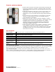
Transfer switch mechanism
•
Transfer switch mechanism is electrically operated and mechanically held
in the Source 1 and Source 2 positions. The transfer switch incorporates
electrical and mechanical interlocks to prevent inadvertent interconnection
of the sources.
• Independent break-before-make action is used for 3-pole switches. This
design allows control of the operating speed of the transfer switch for
proper transfer of motor and rectifier-based loads (programmed transition
feature).
• Electrical interlocks prevent simultaneous closing signals to normal and
emergency contacts and interconnection of normal and emergency
sources through the control wiring.
• High pressure silver alloy contacts resist burning and pitting. Separate
arcing surfaces further protect the main contacts. Contact wear is reduced
by multiple leaf arc chutes that cool and quench the arcs. Barriers
separate the phases to prevent interphase flashover. A transparent
protective cover allows visual inspection while inhibiting inadvertent
contact with energized components.
• Switch mechanism, including contact assemblies, is third-party certified to
verify suitability for applications requiring high endurance switching
capability for the life of the transfer switch. Withstand and closing ratings
are validated using the same set of contacts, further demonstrating the
robust nature of the design.
Specifications
Arc interruption
Multiple leaf arc chutes cool and quench the arcs. Barriers prevent interphase flashover.
Neutral bar
A full current-rated neutral bar with lugs is standard on enclosed 3-pole transfer switches.
Auxiliary contacts
Two contacts (one for each source) are provided for customer use. Wired to terminal block for easy access.
Rated at 10A continuous and 250 VAC maximum.
Operating temperature
-22 oF (-30 oC) to 140 oF (60 oC)
Storage temperature
-40 °F (-40 °C) to 140 °F (60 °C)
Humidity
Up to 95% relative, non-condensing
Altitude
Up to 10,000 ft (3,000 m) without derating
Total transfer time
(source-to-source)
Will not exceed 6 cycles at 60 Hz with normal voltage applied to the actuator and without delayed transition
enabled.
Manual operation
handles
Transfer switches are equipped with permanently attached operating handles and quick-break, quick-make
contact mechanisms suitable for manual operation under de-energized conditions.
Open transition/programmed – Controls the time required for the device to switch from source to source, so that
the load-generated voltages decay to a safe level before connecting to an energized source. Recommended by NEMA
MG-1 to prevent nuisance tripping breakers and load damage. Adjustable 0-60 seconds, default 0 seconds.
Open transition/in-phase – Initiates open transition transfer when in-phase monitor senses both sources are in
phase. Operates in a break-before-make sequence. Includes ability to enable programmed transition as a backup. If
sources are not in phase within 120 seconds, the system will transfer using programmed transition.